
Circuit breaker arc extinguishing device

A technology of arc extinguishing device and circuit breaker, which is applied in the direction of circuit breaker components, etc., which can solve the problems of low arc striking efficiency in arc extinguishing chamber, arc blowing in arc extinguishing chamber, high risk, etc., and achieve fast and accurate arc striking and prolong Effect of service life, improvement of arc extinguishing capacity and breaking capacity

Pending Publication Date: 2021-03-30
乾友科技有限公司
View PDF1 Cites 1 Cited by
  • Summary
  • Abstract
  • Description
  • Claims
  • Application Information

AI Technical Summary

Problems solved by technology

[0005] Therefore, the technical problem to be solved by the present invention is to overcome the low efficiency of arc striking in the arc extinguishing chamber in the prior art, the arc will burn and break down the conductor part of the static contact, and part of the arc will flow from the foot end of the metal grid to the extinguishing chamber. The arc chamber, which causes the arc blowing in the arc extinguishing chamber to cause re-ignition, is easy to be burned, and has a high risk of problems, so as to provide a safe and reliable circuit breaker with high arc ignition efficiency, preventing arc blowing and re-ignition caused by the arc extinguishing chamber arc extinguishing device

Method used


Image

  • Circuit breaker arc extinguishing device
  • Circuit breaker arc extinguishing device
  • Circuit breaker arc extinguishing device

Examples


Embodiment 1

[0039] Below in conjunction with accompanying drawing this embodiment is described in detail:

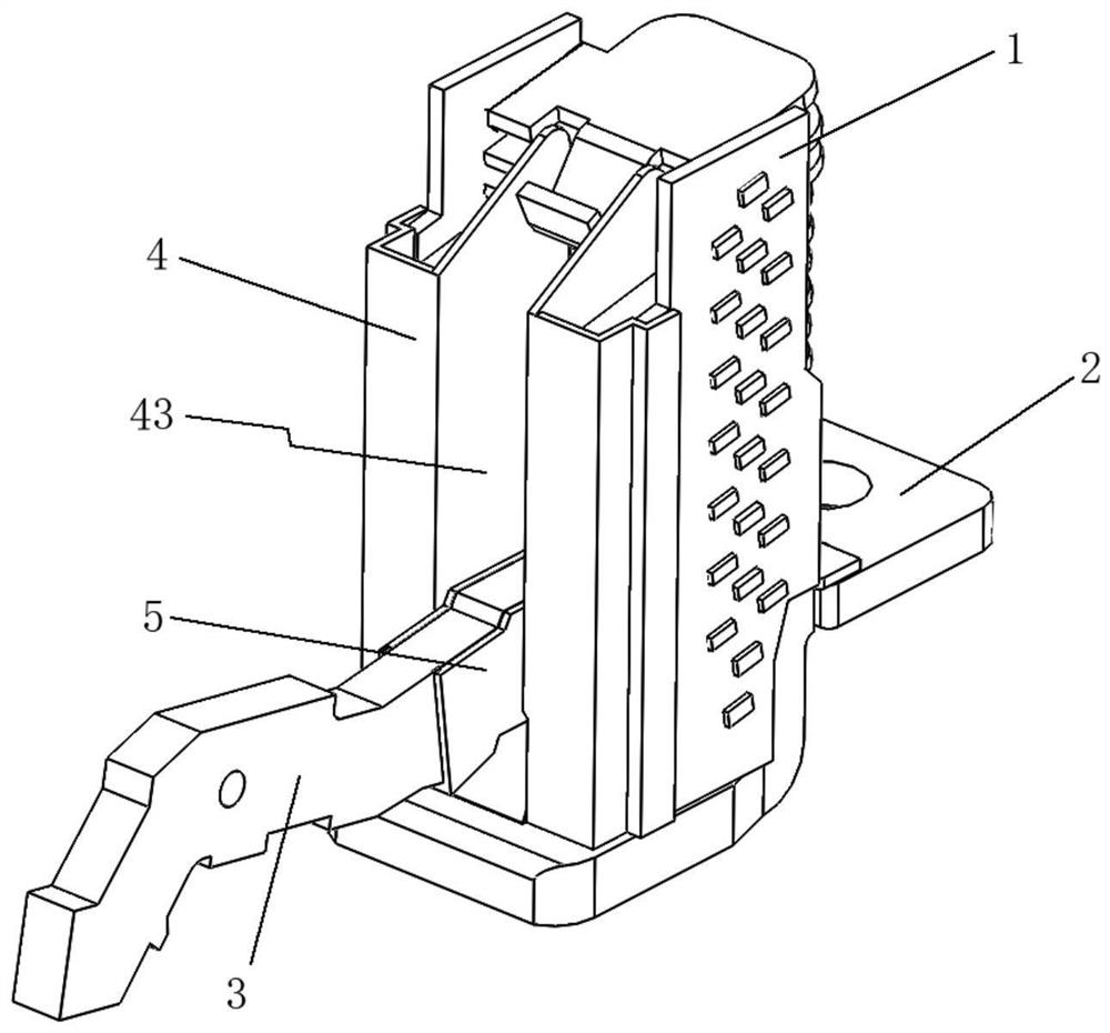
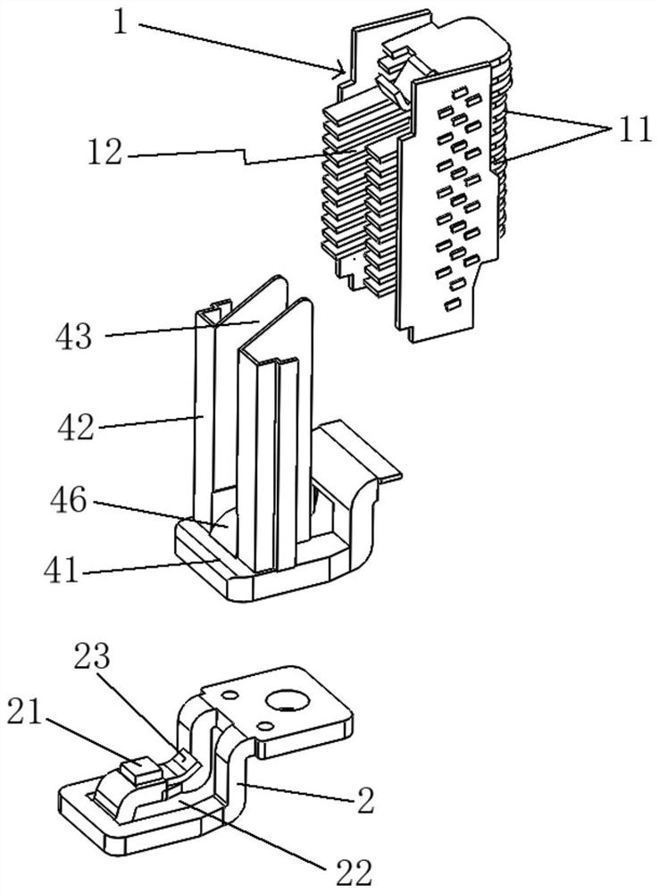
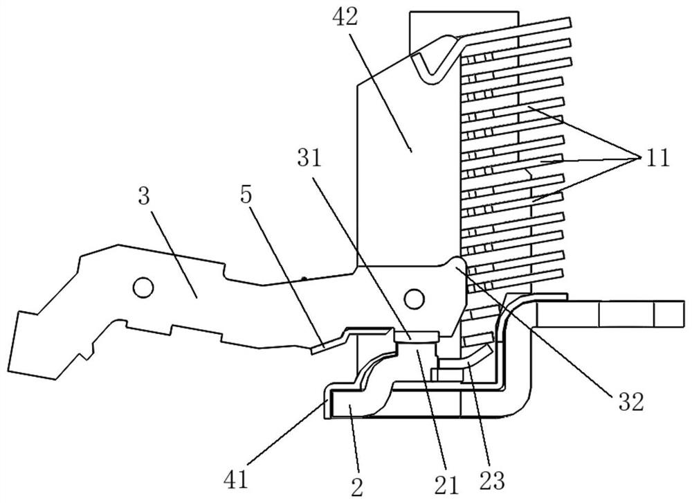
[0040] This embodiment provides as Figure 1-7 A circuit breaker arc extinguishing device shown includes:

[0041] An arc extinguishing chamber 1, in which a plurality of arc extinguishing grids 11 are arranged at intervals, and an arc opening 12 extending along the length direction of the arc extinguishing chamber 1 is formed between the plurality of arc extinguishing grids 11;

[0042] The static contact plate 2, connected to the bottom of the arc extinguishing chamber 1, includes a through-slot hole 22 opposite to the bottom end of the arc-starting opening 12, and is formed in the through-slot hole 22 and opens to the arc-starting A static contact 21 bent and extended on one side;

[0043] The arc shield structure 4 is made of insulating gas-generating material, and is sleeved between the arc extinguishing chamber 1 and the static contact plate 2 along the extending direction o...


PUM


Abstract

A circuit breaker arc extinguishing device comprises an arc extinguishing chamber, a static contact plate, a movable contact plate and an arc isolating sleeve structure arranged between the arc extinguishing chamber and the static contact plate in a sleeving manner. The arc isolating sleeve structure is made of an insulating aerogenesis material, and comprises a lower arc isolating sleeve which surrounds a static contact and covers the static contact plate, and two upper arc isolating sleeves which are oppositely arranged at the two sides of an arc striking opening and wrap the U-shaped pin ends of a plurality of arc extinguishing grid pieces. The arc extinguishing grid pieces and the exposed part of the static contact plate are wrapped and covered through the arc isolating sleeve structure, an arc striking channel directly communicated with the interior of the arc extinguishing chamber is formed, and electric arcs are prevented from flowing to the two sides of the arc striking opening. The arc-isolating sleeve structure made of the insulating aerogenesis material generates a high-temperature gas under the action of the arc, and the arc is blown into the arc extinguishing chamber for arc extinguishing by utilizing an arc blowing effect, so that the resistance of the arc entering the arc extinguishing chamber is reduced, the arc striking efficiency is high, the arc extinguishingefficiency is improved, and the arc extinguishing capability and breaking capability of a circuit breaker are improved.

Description

technical field [0001] The invention relates to the technical field of low-voltage electrical appliances, in particular to an arc extinguishing device for a circuit breaker. Background technique [0002] The arc extinguishing chamber is an important component of the circuit breaker, its function is to extinguish the arc generated on the contact system, and the arc extinguishing grid is installed inside the arc extinguishing chamber. An arc will be generated when the moving and static contacts of the circuit breaker are separated. The moving route of the moving contact is inside the arc extinguishing chamber. Cutting into short arcs in series, thinning the arc and rapidly increasing the arc voltage, thereby extinguishing the arc. When the circuit breaker is short-circuited and broken, the moving and static contacts are repelled to generate an arc. When the arc is generated and enters the arc extinguishing chamber, the arc will meet the side wall of the arc extinguishing cham...

Claims


Application Information

Patent Timeline
IPC IPC(8): H01H73/18
CPCH01H73/18
Inventor 刘艳辉吴炳伟朱健佑卢岳友
Owner 乾友科技有限公司
Learn More