Optical position encoder

A technology of optical encoders and lasers, applied in the field of optical encoders, can solve problems such as large form factors and bill of materials, increase manufacturing costs, and electrical signal errors, and achieve low form factor, low system cost, and low cost effects

Pending Publication Date: 2021-03-30
AMS SENSORS SINGAPORE PTE LTD
View PDF5 Cites 0 Cited by
  • Summary
  • Abstract
  • Description
  • Claims
  • Application Information

AI Technical Summary

Problems solved by technology

This results in a larger form factor and bill of materials, which in turn increases manufacturing costs
In addition, any vibration experienced by the component may cause misalignment of one or more of the LEDs, discs, slits, or photodetectors, which may lead to errors in the electrical signal produced by the system

Method used


Image

  • Optical position encoder
  • Optical position encoder
  • Optical position encoder

Examples


Embodiment Construction

[0056] In general, the present disclosure provides a low-cost optical encoder solution that relies on measured reflections from a moving target to determine the position of the target.

[0057] Some examples of solutions are given in the accompanying drawings.

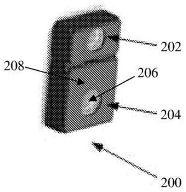
[0058] figure 2 An optical encoder device 200 according to the present disclosure is shown. The optical encoder device 200 includes a transmitter 202 and a sensor module 204 in the form of an IR VCSEL. The sensor module 204 includes a sensor 206 in the form of an IR SPAD, signal conditioning circuitry (not shown), and a processor 208 .

[0059] In use, the emitter 202 is configured to be disposed on a first side of the target to illuminate the target, and the sensor 206 is also configured to be disposed on the first side of the target to sense reflections from the target, wherein the sensed reflection depends on The location of the target within the system.

[0060] In other embodiments, the signal conditioning cir...


PUM


Abstract

An optical encoder system is disclosed comprising a movable target arranged to provide a varying reflectance dependent on a position of the target within the system. An emitter is positioned on a first side of the target to illuminate the target and a sensor is positioned on the first side of the target to sense a reflectance from the target, wherein the sensed reflectance is dependent on the position of the target within the system. Also disclosed are a target and a sensor module for use in such a system, a device comprising such a system and a method of determining the position of a moving target using such a system.

Description

technical field [0001] The present disclosure relates to an optical encoder, and more particularly, but not exclusively, to an optical encoder system and method of determining the position of a moving object using such a system. Background technique [0002] This disclosure relates to optical encoders, which are devices used to measure the position of a target by using the transmission of light to generate a digital signal that follows the position of the target or is fixed to the target or other component associated with the target And change. [0003] Optical encoders come in two types of mechanical configurations: rotary and linear. Rotary encoders are most commonly found in motion control systems, while linear encoders are more specifically used in linear positioning applications such as piston or actuator monitoring systems. [0004] Rotary encoders use optical sensing technology that relies on the rotation of a planar codec disc with a pattern of opaque and transpare...

Claims


Application Information

Patent Timeline
Patent Type & Authority Applications(China)
IPC IPC(8): G01D5/347
CPCG01D5/34776G01D5/3473
Inventor V.埃勒N.格纳尼亚
Owner AMS SENSORS SINGAPORE PTE LTD
Why Eureka
Try Eureka