Anti-exposure magnetic separation equipment for mine

A magnetic separation equipment and mining technology, applied in the direction of magnetic separation, cleaning methods and tools, cleaning methods using tools, etc., can solve the problems of wasting water, interfering with the induction effect of ore, affecting the working process, etc., and achieve the effect of easy observation

Pending Publication Date: 2021-04-02
德清鸿捷铸机有限公司
View PDF7 Cites 1 Cited by
  • Summary
  • Abstract
  • Description
  • Claims
  • Application Information

AI Technical Summary

Problems solved by technology

[0003] At present, the commonly used ore screening methods are divided into water separation and magnetic separation. Water separation mainly uses water to wash ore to achieve the purpose of ore screening. However, since water separation requires a large amount of water, it not only wastes water, but also has great impact on water sources. High requirements, obviously low practicability, and magnetic separation is carried out in the magnetic field of the magnetic separation equipment. Path movement, magnetic products and non-magnetic products can be obtained when they are respectively connected. The existing technology is generally carried out outdoors. Because the outdoor environment is relatively harsh, and at the same time, it often encounters a high temperature exposure environment, which interferes with the ore’s induction of magnetism. effect, will eventually affect the quality of ore sorting work, but direct shading will affect the user's observation of the sorting process and affect the work process. The third component is low, if not separated in time, it will affect the application of subsequent ore

Method used


Image

  • Anti-exposure magnetic separation equipment for mine
  • Anti-exposure magnetic separation equipment for mine
  • Anti-exposure magnetic separation equipment for mine

Examples


Embodiment Construction

[0028] The following will clearly and completely describe the technical solutions in the embodiments of the present invention with reference to the accompanying drawings in the embodiments of the present invention. Obviously, the described embodiments are only some, not all, embodiments of the present invention.

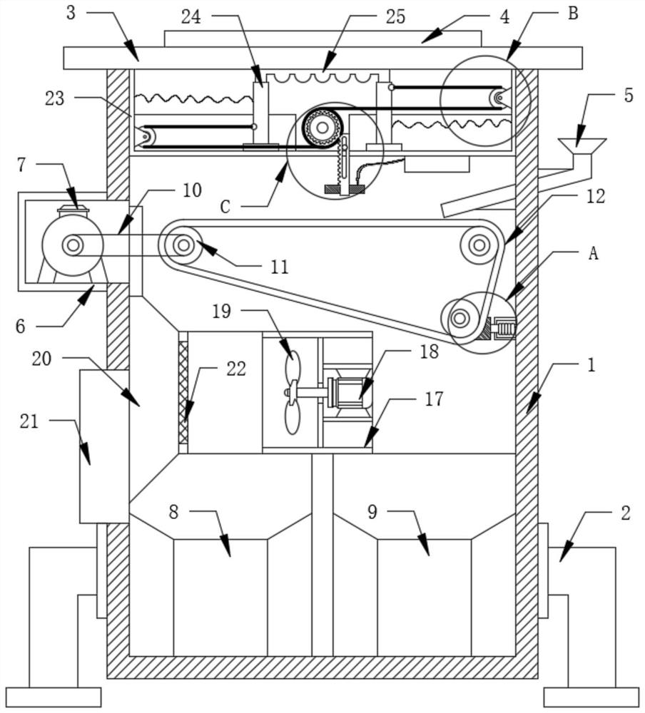
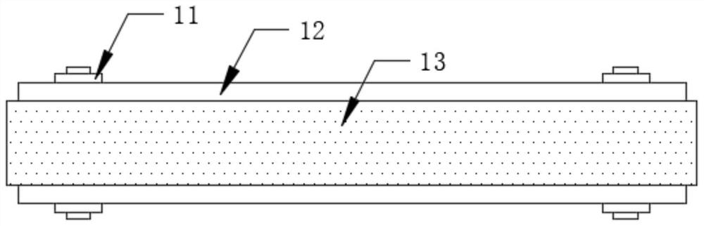
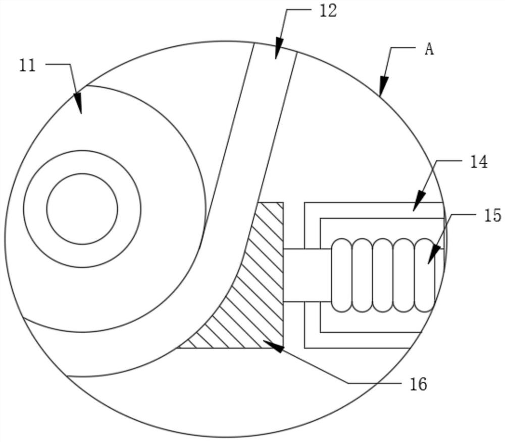
[0029] refer to Figure 1-5 , a kind of anti-exposure mining magnetic separation equipment, comprising a frame body 1, support legs 2, top plate 3, glass sheet 4 and feed port 5, the support legs 2 are fixedly connected to the left and right sides of the lower end of the frame body 1, and the top plate 3 Fixedly connected to the upper side of the frame body 1, the glass sheet 4 is fixedly connected to the upper surface of the top plate 3, the feed inlet 5 is fixedly connected to the right side of the frame body 1, and the left side of the frame body 1 is fixedly connected to the installation frame 6. The inside of the frame 6 is fixedly connected with the first motor...


PUM


Abstract

The invention discloses anti-exposure mine magnetic separation equipment, which comprises a frame body, supporting legs, a top plate, a glass sheet and a feeding port, wherein the supporting legs arefixedly connected to the left side and the right side of the lower end of the frame body, the top plate is fixedly connected to the upper side of the frame body, the glass sheet is fixedly connected to the upper surface of the top plate, the feeding port is fixedly connected to the right side of the frame body, a mounting frame is fixedly connected to the left side of the frame body, a first motoris fixedly connected to the interior of the mounting frame, and a mounting cabinet is fixedly connected to the upper side of the inner wall of the frame body. According to the invention, when the anti-exposure magnetic separation equipment for the mine is used, the effect of convenient sun shading is achieved through cooperative use of structures such as the mounting cabinet, the sliding block, the elastic sun shading cloth and the like; the effect of secondary separation is achieved through cooperative use of structures such as the fan blades, the material guide block, the filter screen andthe like; and the effect of stable scraping is achieved is achieved through cooperative use of structures such as the conveying belt, the magnetic induction belt, the brush block and the like.

Description

technical field [0001] The invention belongs to the technical field of ore separation, and in particular relates to a magnetic separation equipment for mines which is protected from sunlight. Background technique [0002] Ore refers to a mineral aggregate from which useful components can be extracted or it has certain properties that can be used. It can be divided into metallic minerals and non-metallic minerals. Mineral stones and ores can be used in engineering fields such as metal mines and metallurgical industries after crushing, grinding, etc., but the components in the ores are not the same, and generally need to be sorted before actual processing and application . [0003] At present, the commonly used ore screening methods are divided into water separation and magnetic separation. Water separation mainly uses water to wash the ore to achieve the purpose of ore screening. However, because water separation requires a lot of water, it not only wastes water, but also ha...

Claims


Application Information

Patent Timeline
Patent Type & Authority Applications(China)
IPC IPC(8): B03C1/18B08B1/02B08B13/00B07B7/06
CPCB03C1/18B08B1/002B08B1/02B08B13/00B07B7/06
Inventor 陈浩然陈红雷陈锦文王权凯余文博
Owner 德清鸿捷铸机有限公司
Why Eureka
Try Eureka