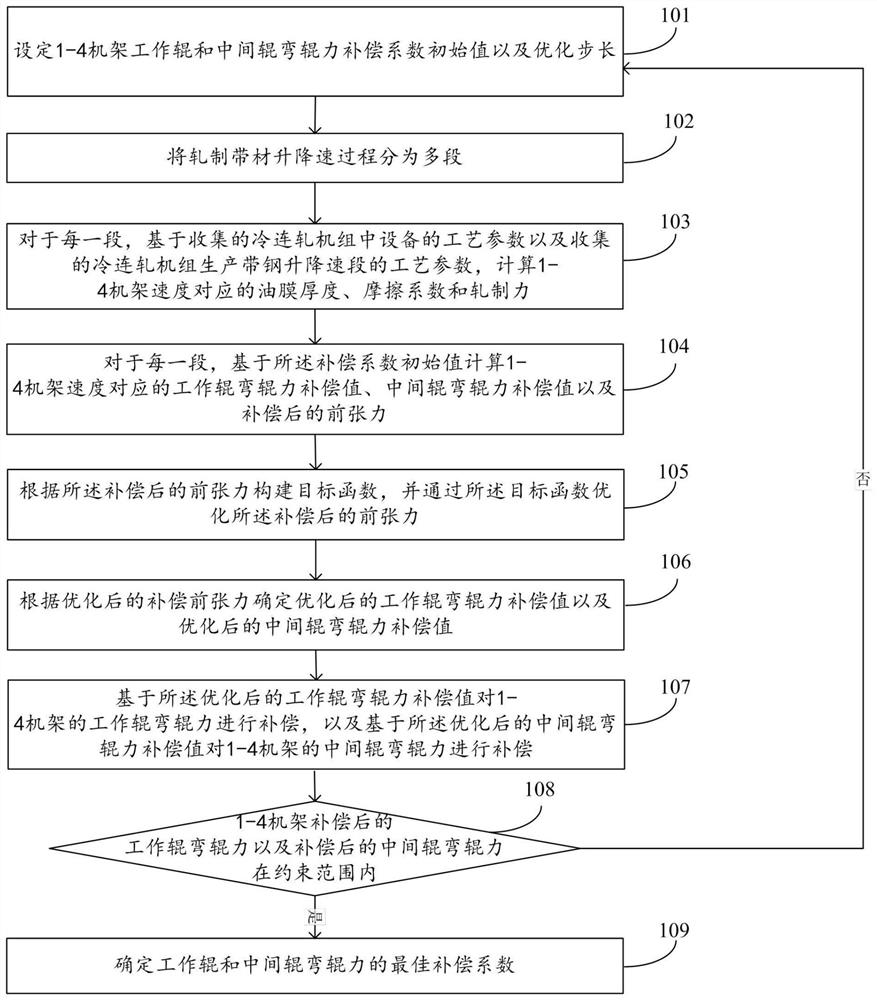
A roll bending compensation method and system aiming at flatness control
A technology of shape control and compensation method, applied in the field of cold rolling, can solve the problems of affecting production or use, poor shape of the lift section, and drastic changes of rolling force, and achieve the effect of small shape fluctuation
- Summary
- Abstract
- Description
- Claims
- Application Information
AI Technical Summary
Problems solved by technology
Method used
Image

Examples
Embodiment 1
[0086] Embodiment 1: The steel type is DV8210A1, and the specification is 1.805*1118mm.
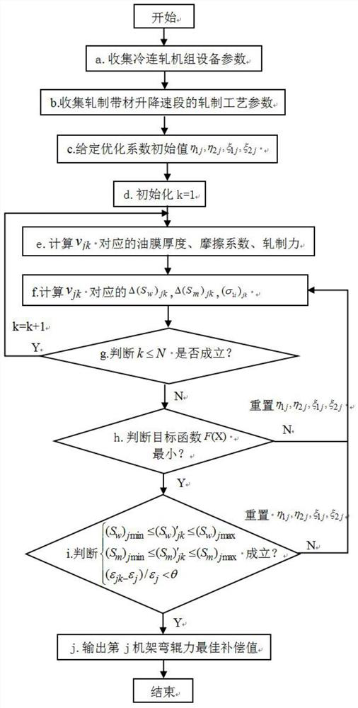
[0087] First, a. Collect the main equipment process parameters of the cold tandem rolling mill, mainly including: 1-5 stand work roll diameter D jw =455mm, intermediate roll diameter D jm =430mm, support roller diameter D jb =1370mm, work roll body length L of 1-5 frame jw =1850mm, intermediate roll body length L jm =1850mm, back-up roller body length L jb =1850mm, the distance between the pressing screws of the 1-5 frame l jw =4050mm, the distance between the middle roller and the screw is l jm =4050mm, the middle distance between the supporting roller and the screw l jb =4070mm, the minimum bending force of the working rolls of 1-5 racks (S w ) jmin =-800KN and maximum bending force (S w ) jmax =800KN, the maximum bending force of the intermediate roll (S m ) jmin =-800KN and minimum bending force (S m ) jmax =800KN, work roll elastic modulus E=210Gpa, work roll Poisson's ...
Embodiment 2
[0121] Embodiment 2: The steel type is DP0161D1, and the specification is 1.621*1170mm.
[0122] First, a. Collect the main equipment process parameters of the cold tandem rolling mill, mainly including: 1-5 stand work roll diameter D jw =455mm, intermediate roll diameter D jm =430mm, support roller diameter D jb =1370mm, work roll body length L of 1-5 frame jw =1850mm, intermediate roll body length L jm =1850mm, back-up roller body length L jb =1850mm, the distance between the pressing screws of the 1-5 frame l jw =4050mm, the distance between the middle roller and the screw is l jm =4050mm, the middle distance between the supporting roller and the screw l jb =4070mm, the minimum bending force of the working rolls of 1-5 racks (S w ) jmin =-800KN and maximum bending force (S w ) jmax =800KN, the maximum bending force of the intermediate roll (S m ) jmin =-800KN and minimum bending force (S m ) jmax =800KN, work roll elastic modulus E=210Gpa, work roll Poisson's ...
PUM
| Property | Measurement | Unit |
|---|---|---|
| width | aaaaa | aaaaa |
| strength | aaaaa | aaaaa |
| width | aaaaa | aaaaa |
Abstract
Description
Claims
Application Information
 - R&D
- Intellectual Property
- Life Sciences
- Materials
- Tech Scout
- Unparalleled Data Quality
- Higher Quality Content
- 60% Fewer Hallucinations
Browse by: Latest US Patents, China's latest patents, Technical Efficacy Thesaurus, Application Domain, Technology Topic, Popular Technical Reports.
© 2025 PatSnap. All rights reserved.Legal|Privacy policy|Modern Slavery Act Transparency Statement|Sitemap|About US| Contact US: help@patsnap.com