
Automatic punching waste collecting device and special punching die

A technology for automatic collection and cutting of waste, applied in feeding devices, positioning devices, storage devices, etc., can solve problems such as hidden dangers, low production efficiency, and high safety, and achieve the effect of improving safety.

Inactive Publication Date: 2021-04-02
李纪真
View PDF1 Cites 3 Cited by
  • Summary
  • Abstract
  • Description
  • Claims
  • Application Information

AI Technical Summary

Problems solved by technology

[0004] 1. In actual production, with the continuous punching, there are about a dozen to dozens of pieces of waste generated on the mold base, and it is necessary to stop the machine to pick up the waste. When picking up the waste, the punching machine must be stopped before it can be cleaned. Waste, low production efficiency;
[0005] 2. When manually cleaning up the waste materials piled up on the mold base, it is necessary to enter the mold by hand, which has great potential safety hazards

Method used


Image

  • Automatic punching waste collecting device and special punching die
  • Automatic punching waste collecting device and special punching die
  • Automatic punching waste collecting device and special punching die

Examples


Embodiment Construction

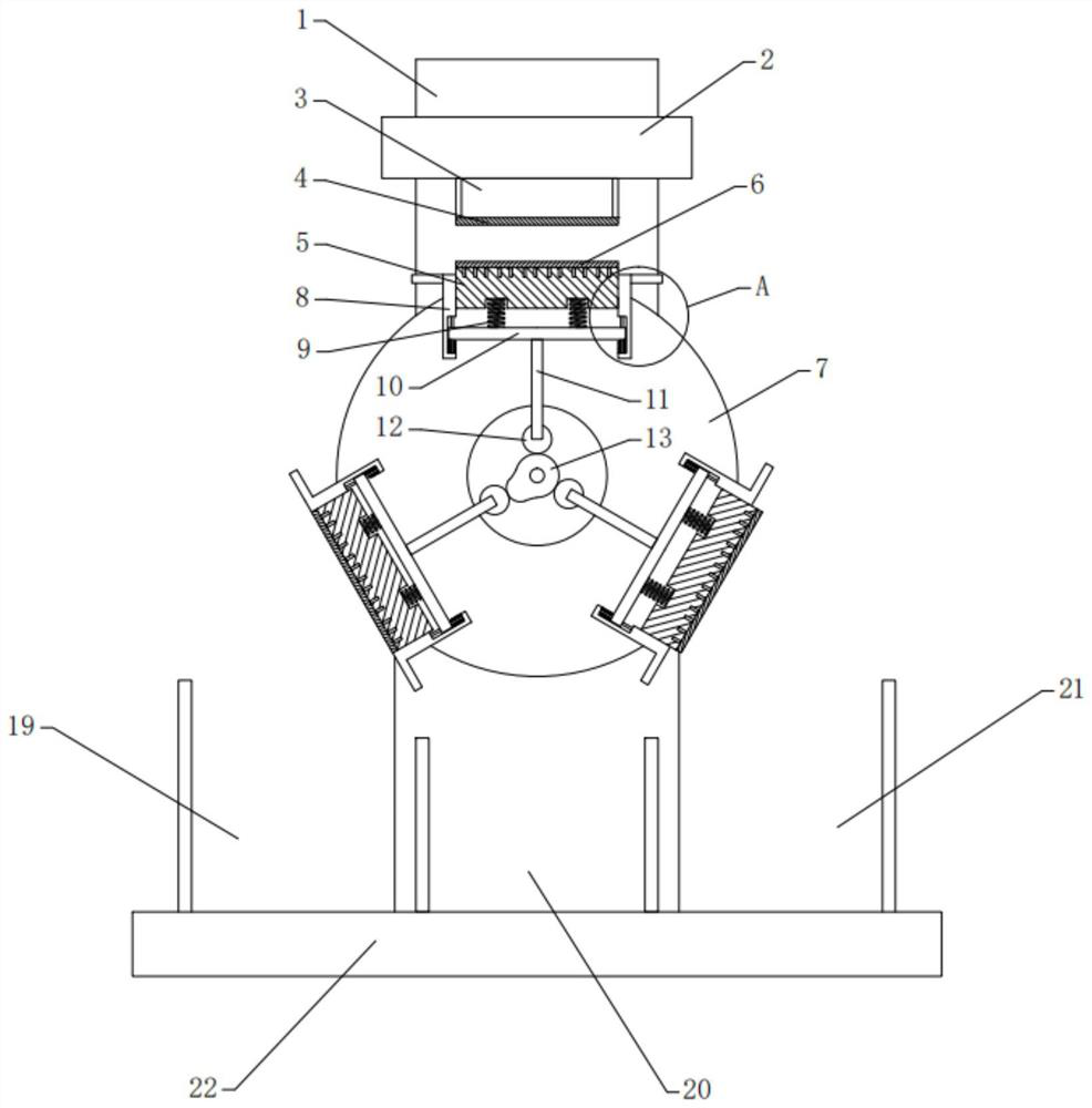
[0027] The following will clearly and completely describe the technical solutions in the embodiments of the present invention with reference to the accompanying drawings in the embodiments of the present invention. Obviously, the described embodiments are only some, not all, embodiments of the present invention. Based on the embodiments of the present invention, all other embodiments obtained by persons of ordinary skill in the art without making creative efforts belong to the protection scope of the present invention.

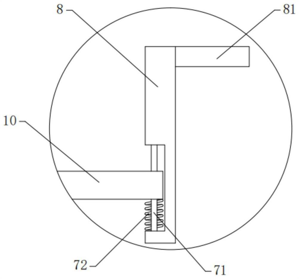
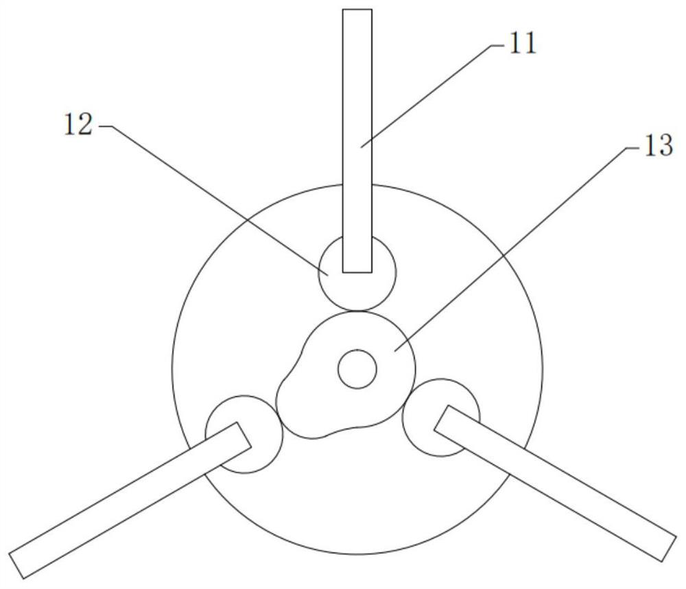
[0028] see Figure 1-6 , the present invention provides a technical solution:

[0029] An automatic collection device for punching waste, comprising

[0030] The punch 2 is movable on the frame 1. The punch 2 can reciprocate up and down along the frame 1. The frame 1 forms the track for the reciprocating movement of the punch 2 up and down. The punch 2 is connected with the power device. Under the action, the punch 2 reciprocates up and down along the frame ...


PUM


Abstract

The invention discloses an automatic punching waste collecting device and a special punching die. The automatic punching waste collecting device comprises a punch, lower female dies, discharging plates and a driving rod, wherein the punch is movably arranged on a rack; an upper female die is fixedly arranged on the punch; an upper cutting edge is arranged on the lower edge of the upper female die;the lower female dies are equidistantly arranged around a driving roller; lower cutting edges corresponding to the upper cutting edges are arranged on the lower female dies; the discharging plates are movably arranged on the side edges of the lower female dies; one end of the driving rod is movably connected with the punch; and the other end of the driving rod is movably connected with one end ofa driving arm. According to the automatic punching waste collecting device and the special punching die provided by the invention, the multiple sets of lower female dies are equidistantly arranged around the driving roller, under the action of a gap driving mechanism composed of a driving wheel, driving teeth, a driven wheel and the like, after the lower female dies and the upper female die are subjected to die assembly punching, along with continuous rotation of the driving roller, finished products are kept still and cannot fall off under the action of adsorption holes, and punching waste falls into a waste bin under the action of gravity, so that the collection of the punching wastes is realized.

Description

technical field [0001] The invention relates to the technical field of punching die equipment, in particular to an automatic punching waste collection device and a special punching die. Background technique [0002] Stamping die is a special process equipment for processing metal or non-metal materials into parts or semi-finished products in cold stamping processing, called cold stamping die, commonly known as cold stamping die. Stamping is a pressure processing method that uses a mold installed on a press to apply pressure to the material at room temperature to cause separation or plastic deformation to obtain the required parts. Chinese patent CN201710598456.6 discloses a stamping die for sheet metal strips, including: spring pressure columns, stamping die bases, horizontal fixing rods, die stamping plates, movable clearance holes, transverse centering holes, spring fixing holes, movable There are two clearance holes and transverse centering holes arranged in a straight l...

Claims


Application Information

Patent Timeline
Patent Type & Authority Applications(China)
IPC IPC(8): B21D28/02B21D43/20
CPCB21D28/02B21D43/20
Inventor 不公告发明人
Owner 李纪真
Learn More