

Cable shearing device for relay protection
A relay protection and cutting device technology, which is applied in the field of cable cutting devices, can solve problems such as the inability to meet the cutting needs of cables of different lengths, and achieve the effect of preventing incomplete cutting of cables and increasing the cutting speed
- Summary
- Abstract
- Description
- Claims
- Application Information
AI Technical Summary
Problems solved by technology
Method used
Image

Examples
Embodiment 1
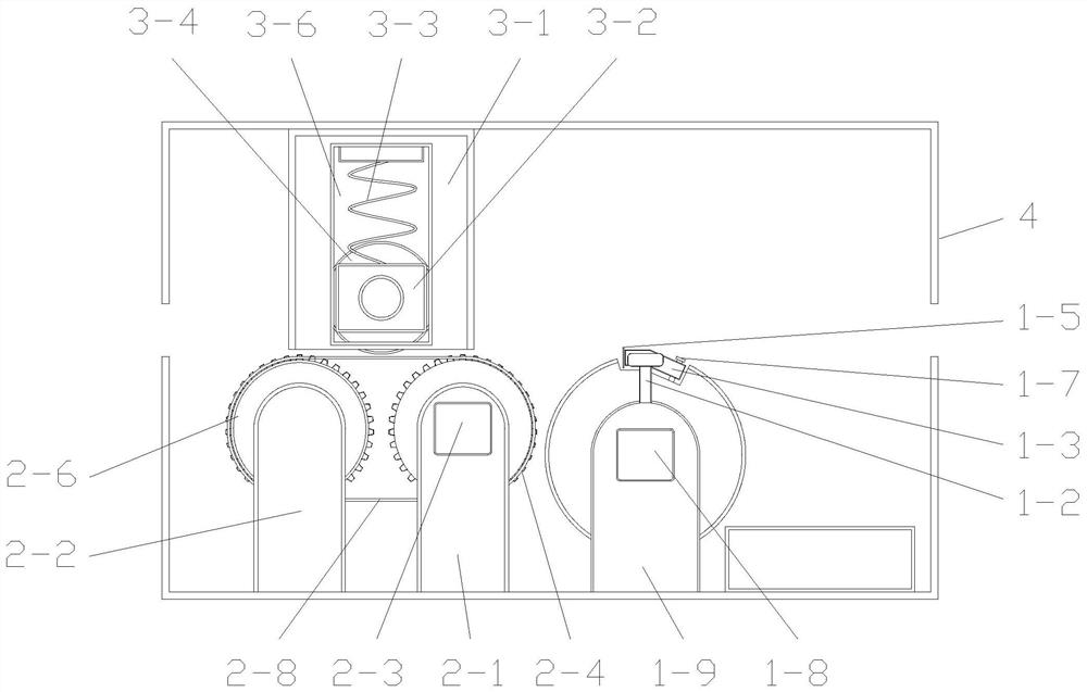
[0082] Such as figure 1 As shown, a relay protection cable cutting device includes a cutting mechanism, a transmission mechanism, a limit mechanism and an outer frame 4 . The limit mechanism is arranged above the transmission mechanism for pressing the cable on the transmission mechanism; the shear mechanism is arranged on the right side of the transmission mechanism; the transmission mechanism and the shear mechanism are installed at the bottom of the inner wall of the outer frame 4, and the limit mechanism is installed At the top of the inner wall of the outer frame 4.
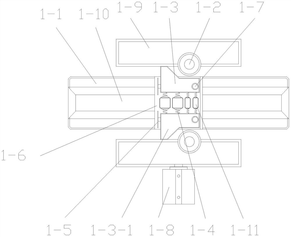
[0083] Such as Figure 3~5 As shown, the above-mentioned shearing mechanism includes two first supporting columns 1-9, a first rotating motor 1-8, a shearing wheel 1-1, two limit cylinders 1-2, a clamping assembly, and two blades 1 -5. Two second rotating motors 1-13, four support rollers 1-11; the clamping assembly includes two fixed cylinders 1-7, two connecting blocks 1-3, and a first telescopic compone...
Embodiment 2
[0088] The difference between this embodiment and Embodiment 1 is that the limiting cylinder 1-2 realizes the self-rotation of the limiting cylinder 1-2 through rotational connection with the first supporting column 1-9.
[0089] During the clamping process of the limiting cylinder 1-2 by squeezing the two opposite connecting blocks 1-3, the rotation of the limiting cylinder 1-2 can reduce the friction between it and the connecting block 1-3, thus The wear of both can be reduced, and at the same time, the rotation of the shearing wheel 1-1 can be prevented from being hindered.
Embodiment 3
[0091] The difference between this embodiment and Embodiment 1 is that two notches 1-6 are provided at equal intervals on the peripheral surface of the shearing wheel 1-1, and a set of clamping components is provided in each notch 1-6. The total number of blades 1-5 and the second rotating motor 1-13 is four, and the total number of thread support rollers 1-11 is eight.
[0092] By arranging two notches 1-6 at equal intervals, the shearing wheel 1-1 can realize two shears by rotating one revolution, and can reduce the rotational speed of the shearing wheel 1-1 under the condition that the required cable cutting length is the same , thereby reducing the energy consumption during the operation of the first rotating electric machine 1-8.
PUM
 Abstract
Description
Claims
Application Information