Automatic screen printing equipment for keycaps for keyboard printing

A keycap, automatic technology, used in printing, printing presses, rotary printing presses, etc., can solve the problems of low work efficiency, inability to guarantee printing quality, long consumption time, etc., to achieve the effect of clamping effect

Inactive Publication Date: 2021-04-02
唐健常
View PDF1 Cites 5 Cited by
  • Summary
  • Abstract
  • Description
  • Claims
  • Application Information

AI Technical Summary

Problems solved by technology

[0005] In order to overcome the shortcomings of traditional keycap printing, such as long time consumption, low work efficiency and inability to guarantee printing quality, the technical problem to be solved is to provide an automatic screen printing keycap for keyboard printing with short time consumption, high work efficiency and guaranteed printing quality equipment

Method used


Image

  • Automatic screen printing equipment for keycaps for keyboard printing
  • Automatic screen printing equipment for keycaps for keyboard printing
  • Automatic screen printing equipment for keycaps for keyboard printing

Examples


Embodiment 1

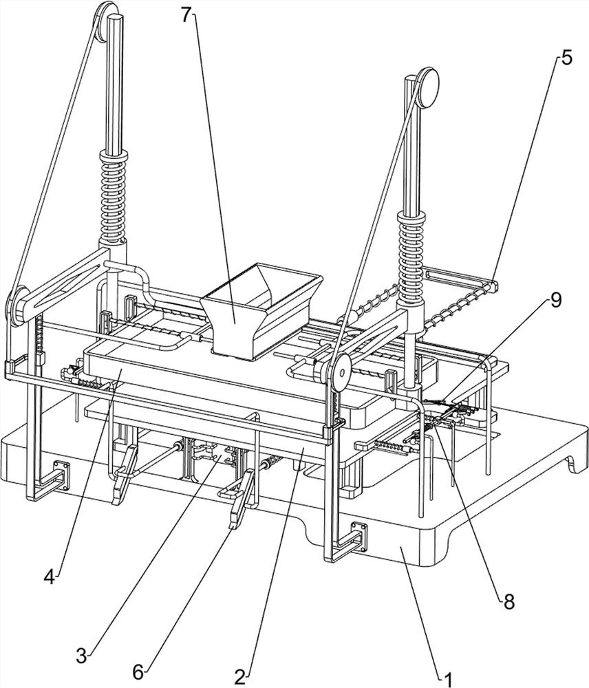
[0059] An automatic screen printing equipment for keycaps for keyboard printing, such as figure 1 As shown, it includes a bottom plate 1, a workbench 2, a cylinder 3, a printing mechanism 4, and a pushing mechanism 5. A workbench 2 is arranged in the upper middle of the bottom plate 1, and a cylinder 3 is installed in the middle of the lower side of the workbench 2. The upper rear of the bottom plate 1 Printing mechanisms 4 are arranged on the left and right sides, and a pushing mechanism 5 is arranged in the middle part of the upper front side of the bottom plate 1 .

[0060] When people want to print the keycaps on the keyboard, they can use this automatic screen printing equipment for keycaps for keyboard printing. First, the user places the unprinted keyboard on the workbench 2, starts the cylinder 3, and is in the elongated state. The telescopic rod of the cylinder 3 under the state is shortened backwards, thereby driving the pushing mechanism 5 to move backward, pushing ...

Embodiment 2

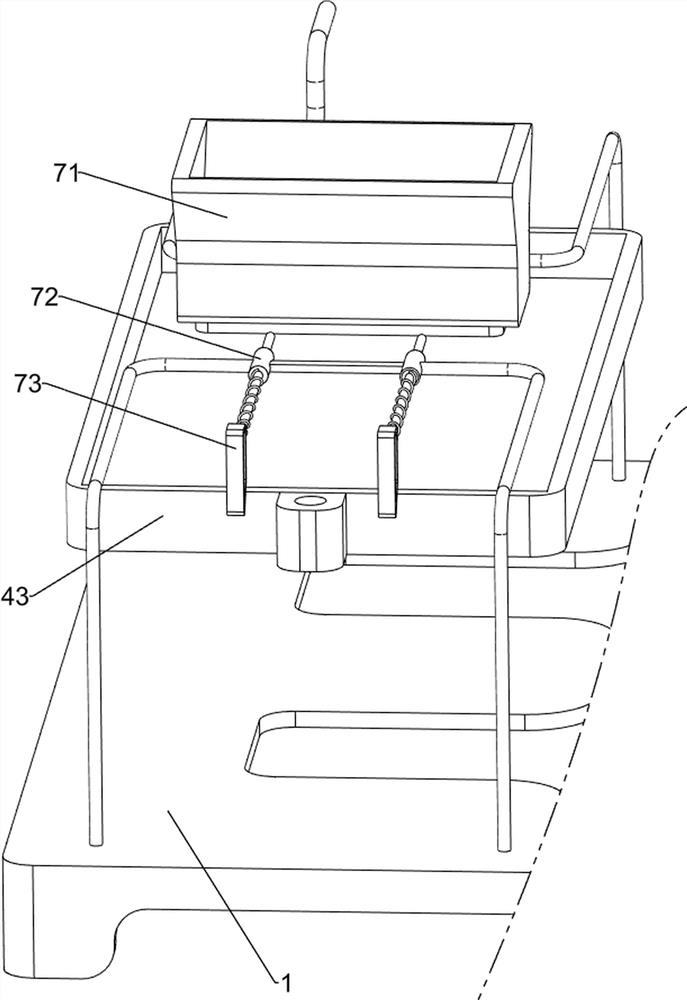
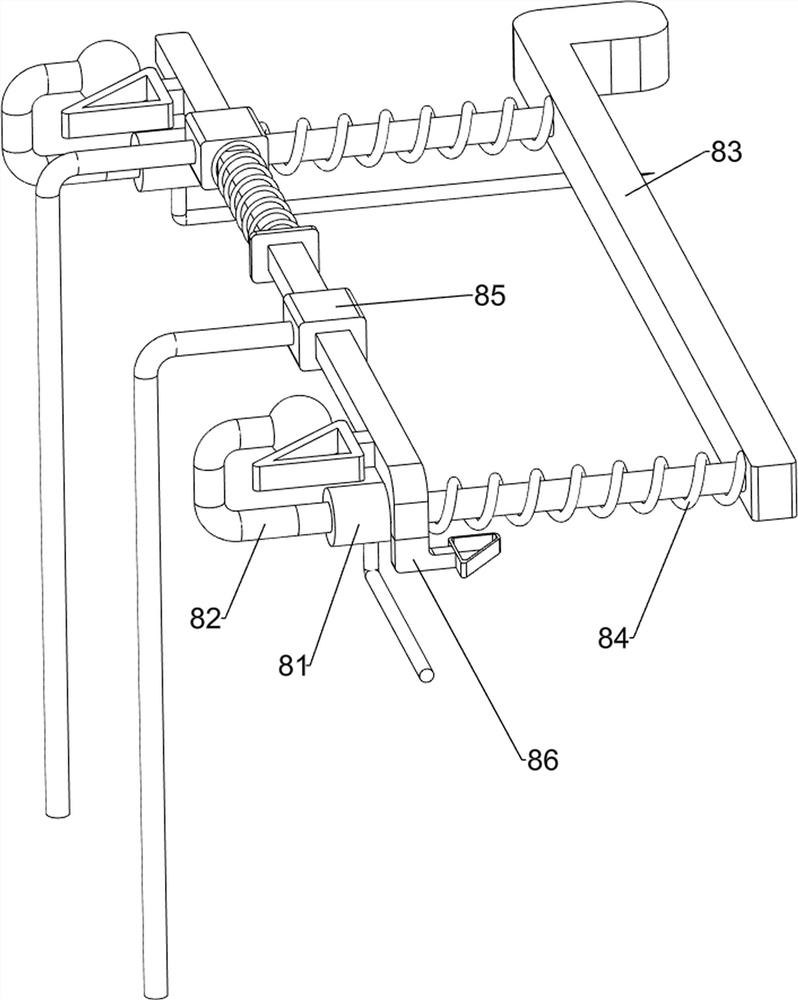
[0062] On the basis of Example 1, such as figure 2 with image 3As shown, the printing mechanism 4 includes a first guide sleeve 41, an elastic sliding rod 42, a silk screen box 43, a pulling assembly 44, a sliding block 45 and a tension spring 46, and the left and right sides of the rear wall on the bottom plate 1 are provided with first guides. Cover 41, the upper part of each first guide sleeve 41 is slidably provided with an elastic sliding rod 42, and a silk screen box 43 is connected between the two elastic sliding rods 42 bottoms, and each elastic sliding rod 42 top is connected with the first guide sleeve 41 are connected with pulling assembly 44, and each pulling assembly 44 bottom is all provided with sliding block 45, and sliding block 45 is connected with the first guide sleeve 41 slidingly, between each sliding block 45 and the first guide sleeve 41 A tension spring 46 is attached.

[0063] The user injects paint into the screen printing box 43, pulls the slidi...

Embodiment 3

[0067] On the basis of Example 2, such as Figure 4-Figure 8 As shown, a pressing mechanism 6 is also included, and the middle part of the rear side of the bottom plate 1 is provided with a pressing mechanism 6. The pressing mechanism 6 includes a third guide sleeve 61, a connecting rod wedge 62, a first elastic wedge assembly 63 and The elastic small block assembly 64, the middle part of the upper rear side of the base plate 1 is provided with a third guide sleeve 61, and a connecting rod wedge block 62 is provided between the bottoms of the two sliding blocks 45, and each third guide sleeve 61 top is slidably provided with The first elastic wedge block assembly 63 , the first elastic wedge block assembly 63 is in contact with the connecting rod wedge block 62 , and each first elastic wedge block assembly 63 is provided with an elastic small block assembly 64 on the front side.

[0068] When the moving plate 53 moves forward, the moving plate 53 contacts and cooperates with t...


PUM


Abstract

The invention relates to printing equipment, in particular to automatic screen printing equipment for keycaps for keyboard printing. The automatic screen printing equipment for the keycaps for keyboard printing is short in consumed time, high in working efficiency and capable of guaranteeing the printing quality. The automatic screen printing equipment for the keycaps for keyboard printing comprises a bottom plate, an air cylinder, printing mechanisms and a pushing mechanism, wherein a workbench is arranged in the middle of the bottom plate; the air cylinder is mounted in the middle of the lower side of the workbench; the printing mechanisms are arranged on the left side and the right side of the rear wall of the bottom plate; and the pushing mechanism is arranged in the middle of the upper front wall of the bottom plate. An elastic sliding rod is driven to move downwards by stretching a pulling assembly, then a screen printing box is driven to move downwards, a keyboard on the workbench is printed, and the printing effect is achieved.

Description

technical field [0001] The invention relates to a printing device, in particular to an automatic silk screen printing device for keycaps for keyboard printing. Background technique [0002] There are generally corresponding text or patterns printed on the keycaps. In the traditional keycap printing process, most of the operations are done manually by workers. Due to the large number of keycaps, printing processing It brings a lot of extra trouble. Before printing, different processes need to be adjusted to print corresponding to different keycaps. This process not only consumes a long time, but also increases the difficulty of the work and reduces the quality of printing. [0003] Patent application CN203228486U, with a publication date of 20131009, discloses a structurally improved keycap printing device, including a placement groove, a positioning column, a buckle, a positioning rib, a protrusion, a drainage hole, an upper cover and a lower cover. Put the keycap into the ...

Claims


Application Information

Patent Timeline
Patent Type & Authority Applications(China)
IPC IPC(8): B41F15/08B41F15/14B41F15/40
CPCB41F15/08B41F15/14B41F15/40
Inventor 唐健常
Owner 唐健常
Why Eureka
Try Eureka