
A mechanical parts pushing device

A technology for pushing devices and mechanical parts, applied in metal processing and other directions, can solve the problems of reducing part processing efficiency, parts change, parts transportation, etc., and achieve the effect of improving processing efficiency and reducing labor and time costs.

Active Publication Date: 2021-10-01
绵阳鸿悦圣达科技有限公司
View PDF0 Cites 0 Cited by
  • Summary
  • Abstract
  • Description
  • Claims
  • Application Information

AI Technical Summary

Problems solved by technology

In the process of parts transportation, parts are often transported to the processing position. Since the parts cannot be directly transported to the accurate processing position on the conveyor belt, the parts can only be stacked in front of the processing position when they are transported. Sometimes even due to the heavy workload, the parts When transported and stacked, due to the conveyor belt, the position of the parts is easy to change, which requires manual processing, which wastes a lot of time and reduces the processing efficiency of the parts

Method used


Image

  • A mechanical parts pushing device
  • A mechanical parts pushing device
  • A mechanical parts pushing device

Examples


Embodiment Construction

[0032] The technical solution of the present invention will be further described in detail below in conjunction with the accompanying drawings, but the protection scope of the present invention is not limited to the following description.

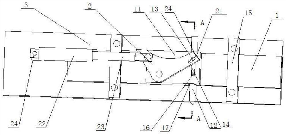
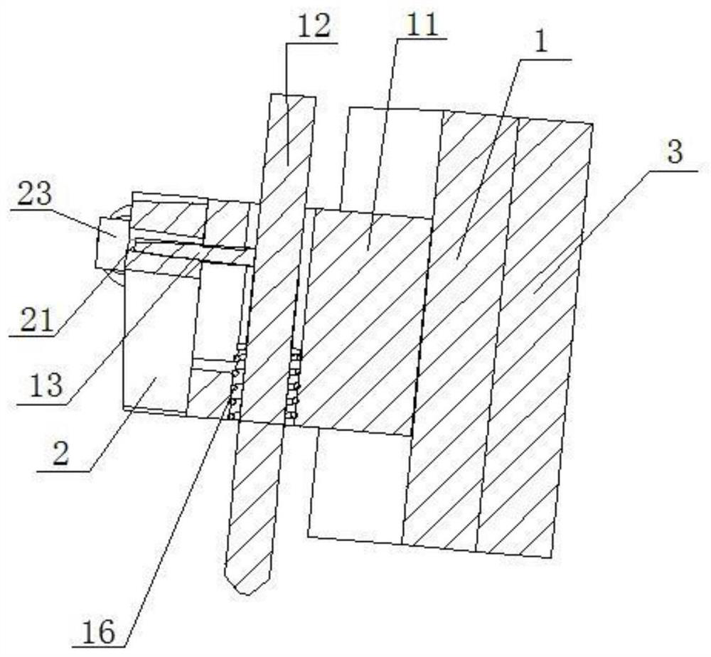
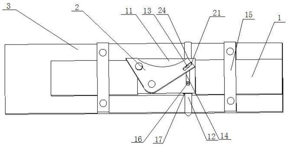
[0033] like Figure 1 to Figure 6As shown, a mechanical parts pushing device includes a sliding mechanism and a pushing mechanism; the sliding mechanism includes a sliding plate 1, and a guiding structure for guiding the sliding plate 1 is provided on the sliding plate 1; a sliding shell 11 is fixed on the sliding plate 1, and the sliding shell 11 runs through A movable push rod 12 is pierced, and a movable shaft 13 is fixed on the push rod 12, and the movable shaft 13 is perpendicular to the axis line of the push rod 12, and a chute 14 matching the movable shaft 13 is opened on the sliding shell 11 , one end of the movable shaft 13 moves through the chute, and one end of the movable shaft 13 is connected with the push mechanism; the movabl...


PUM


Abstract

The present invention discloses a mechanical parts push device involving the field of mechanical transportation, including sliding mechanisms and push agencies; sliding mechanisms include skateboarding, the skateboards are equipped with guidelines for skateboarding.Wear the push rod with activity, the active shaft is fixed on the push rod, and the active axis vertical and the axis of the push rod. The sliding shell is opened on the sliding shell with a slide with the active shaft.Too sliding, and connecting one end of the active axis to the push agency; the push agency includes hinge blocks, hinge blocks and sliding shell movements, and the hinge block is opened with a active axis.The hydraulic rod of the hinge block activity.The push device can easily push the machine parts that need to be processed from the conveyor belt to the position of the next processing process, while reducing labor and time costs, and improving processing efficiency.

Description

technical field [0001] The invention relates to the field of mechanical transportation, in particular to a mechanical part pushing device. Background technique [0002] In the process of machining mechanical parts, there are often many parts that need to be further processed before they can be used. In the process of parts transportation, parts are often transported to the processing position. Since the parts cannot be directly transported to the accurate processing position on the conveyor belt, the parts can only be stacked in front of the processing position when they are transported. Sometimes even due to the heavy workload, the parts After being transported and stacked, the position of the parts is easy to change due to the conveyor belt, which requires manual processing, which wastes a lot of time and reduces the processing efficiency of the parts. Contents of the invention [0003] The purpose of the present invention is to overcome the deficiencies of the prior ar...

Claims


Application Information

Patent Timeline
Patent Type & Authority Patents(China)
IPC IPC(8): B23Q7/00B23Q7/06
CPCB23Q7/00B23Q7/06
Inventor 周海英
Owner 绵阳鸿悦圣达科技有限公司
Learn More