
Rotatable rear towing hook for vehicle and vehicle

A towing hook and rear towing technology, applied in vehicle parts, traction connectors, transportation and packaging, etc., can solve the problem that the rear towing hook cannot be satisfied at the same time, the vehicle departure angle becomes smaller, and the support seat and the frame tail beam are prone to appear. problems, etc.

Pending Publication Date: 2021-04-02
DONGFENG OFF ROAD VEHICLE CO LTD
View PDF1 Cites 2 Cited by
  • Summary
  • Abstract
  • Description
  • Claims
  • Application Information

AI Technical Summary

Problems solved by technology

The rear towing hook of the existing structure cannot meet the above requirements at the same time
[0003] Chinese patent CN102431401A proposes a lubricating and sealing device for a full-hung traction hook. When the traction hook is used on a central axle trailer or on off-road roads, the supporting seat and the rear beam of the frame are prone to failure due to excessive force in the up and down direction.
When the length of the support seat is increased, the length of the towing hook will increase accordingly, which will cause the problem that the departure angle of the vehicle will become smaller
[0004] Based on the above-mentioned defects and deficiencies, it is urgently needed in this field to further improve the design of the existing towing hook, to build a safe, reliable, and strong enough towing hook. On the premise of not changing the length of the towing hook, by changing the force transmission mode, In order to solve the problem of increasing the strength by increasing the length of the rear towing hook due to the minimum ground clearance and departure angle of the off-road vehicle in the prior art

Method used


Image

  • Rotatable rear towing hook for vehicle and vehicle
  • Rotatable rear towing hook for vehicle and vehicle
  • Rotatable rear towing hook for vehicle and vehicle

Examples


Embodiment Construction

[0031] In order to make the object, technical solution and advantages of the present invention clearer, the present invention will be further described in detail below in conjunction with the accompanying drawings and embodiments. It should be understood that the specific embodiments described here are only used to explain the present invention, not to limit the present invention. In addition, the technical features involved in the various embodiments of the present invention described below can be combined with each other as long as they do not constitute a conflict with each other.

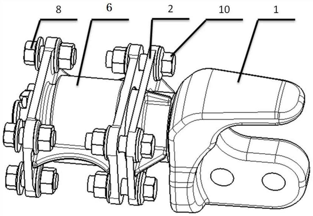
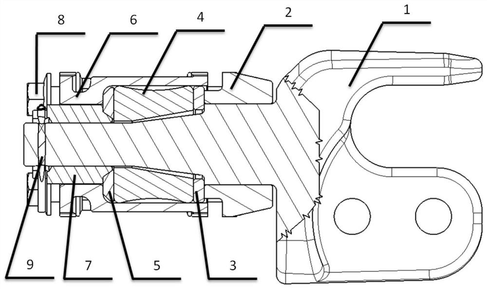
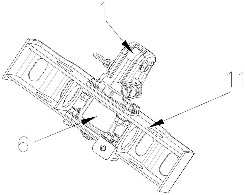
[0032] Such as figure 1 with figure 2As shown, a rotatable rear tow hook for a vehicle provided by the embodiment of the present invention includes a tow hook 1, a lock nut 7, a buffer block 4 and a front support seat 2 arranged in sequence on the outer periphery of the tow hook, wherein the The lock nut 7 is fixedly arranged at the end of the towing hook 1; the outer periphery of the lock nu...


PUM


Abstract

The invention belongs to the technical field of vehicle accessories, and particularly discloses a rotatable rear towing hook for a vehicle and the vehicle. The rotatable rear towing hook comprises a towing hook and also comprises a locking nut, a buffer block and a front supporting seat, which are sequentially arranged on the periphery of the towing hook. A rear supporting seat is arranged on theperiphery of the locking nut, one end of the rear supporting seat is connected with the locking nut, the other end extends to the front supporting seat, and the periphery of the rear supporting seat is fixedly connected with a frame through a rear supporting seat fixing bolt. A cavity for accommodating the buffer block is formed between the rear supporting seat and the towing hook; the periphery of the front supporting seat is fixedly connected with the frame through a front supporting seat fixing bolt, an opening used for allowing the towing hook to penetrate through is formed in the middle of the front supporting seat, the front supporting seat is connected with the towing hook in a shaft fit mode, and the towing hook can rotate or slide front and back along the front supporting seat. Onthe premise that the length of the towing hook is not changed, backward pulling force, forward pushing force and vertical force transmitted to the towing hook by a trailer can be borne.

Description

technical field [0001] The invention belongs to the technical field of vehicle accessories, and more specifically relates to a rotatable rear tow hook for a vehicle and a vehicle. Background technique [0002] The rear tow hook of off-road vehicles is used to tow the central axle trailer, etc. When driving on off-road roads, it bears a large force in the up and down direction, so the rear tow hook is required to have high strength. However, the minimum ground clearance and departure angle of off-road vehicles limit the strength of the rear tow hook by increasing its length. The rear towing hook of the existing structure cannot satisfy the above-mentioned requirements simultaneously. [0003] Chinese patent CN102431401A proposes a lubricating and sealing device for a fully-hung traction hook. When the traction hook is used for a central axle trailer or off-road, the support seat and the tail beam of the vehicle frame are prone to failure due to excessive force in the up and ...

Claims


Application Information

Patent Timeline
Patent Type & Authority Applications(China)
IPC IPC(8): B60D1/52B60D1/48B60D1/24B60D1/04
CPCB60D1/52B60D1/488B60D1/244B60D1/04
Inventor 吕超郭东卿赵智索联兵
Owner DONGFENG OFF ROAD VEHICLE CO LTD
Learn More