
Transfer platform of carrier

A transfer platform and carrier technology, applied in packaging and other directions, can solve the problems of high use cost and large footprint of the feeding robot, and achieve the effect of solving the limited space

Active Publication Date: 2021-04-02
JIANGXI WONDERFUL CERAMICS CO LTD +2
View PDF9 Cites 0 Cited by
  • Summary
  • Abstract
  • Description
  • Claims
  • Application Information

AI Technical Summary

Problems solved by technology

[0003] The purpose of the present invention is to provide a transfer platform for the carrier that solves the problems of the existing loading robot with too large footprint and high cost of use

Method used


Image

  • Transfer platform of carrier
  • Transfer platform of carrier
  • Transfer platform of carrier

Examples


Embodiment Construction

[0026] The present invention will be described in further detail below in conjunction with accompanying drawing:

[0027] The preferred embodiments of the present invention are described in detail below with reference to the accompanying drawings, so that the advantages and features of the present invention can be more easily understood by those skilled in the art, and the protection scope of the present invention can be more clearly defined. The directional terms mentioned in the present invention, such as "up", "down", "front", "back", "left", "right", "top", "bottom", etc., are only for reference to the attached drawings. direction. Therefore, the directional terms used are used to illustrate and understand the present invention, but not to limit the present invention.

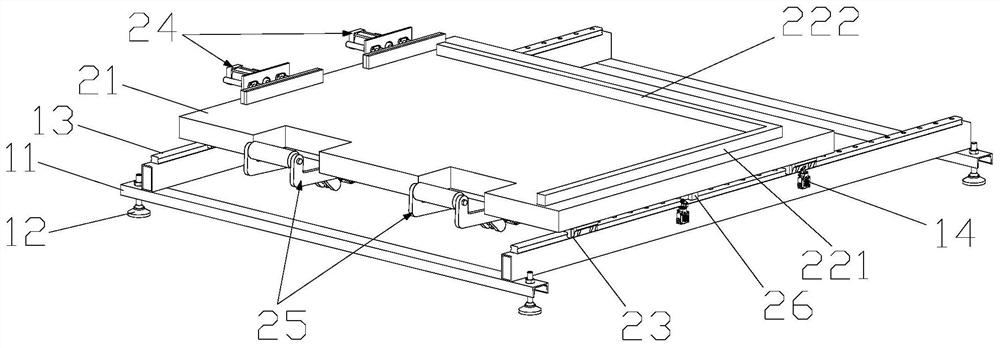
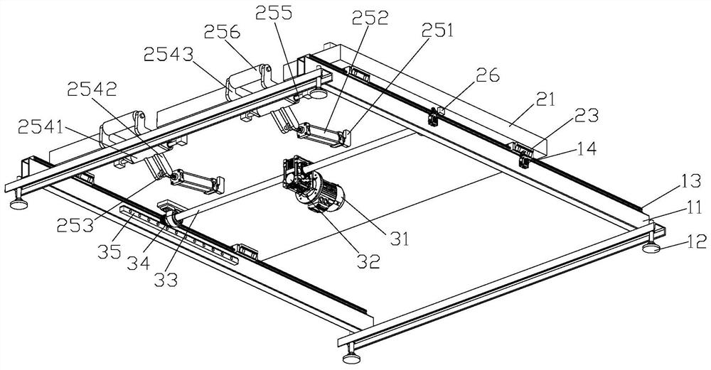
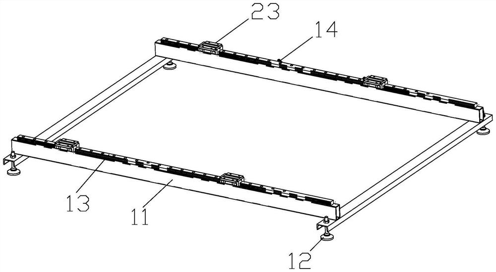
[0028] see figure 1 , figure 2 As shown, a transfer platform for transferring an A-shaped object carrier 4 includes a base, a transfer mechanism, and a loading mechanism. On the provided linear guide r...


PUM


Abstract

The invention relates to a transfer platform of a carrier. The transfer platform comprises a base, a transfer mechanism and a carrying mechanism, wherein the carrying mechanism is movably installed onlinear guide rails fixedly arranged on the two sides of the base through sliding blocks fixedly arranged on the two sides of the bottom surface, the transfer mechanism is fixedly arranged on the bottom surface of the carrying mechanism, and the transfer mechanism provides driving force for the the carrying mechanism to carry out reciprocating motion along the linear guide rails. According to thetransfer platform of the carrier, the carrier on the carrying mechanism can be accurately positioned, the position accuracy of the carrier in the packaging process can be improved further due to the positioning accuracy of the transfer mechanism, and the it is avoided that a ceramic plate is damaged due to poor positioning. In addition, the problems of site limitation and insufficient moving rangein the mechanical arm packaging process can be solved.

Description

technical field [0001] The invention relates to the field of transfer of ceramic tiles, in particular to a transfer platform of a carrier. Background technique [0002] In the past three or two years, due to its advantages such as minimizing collage traces, highlighting the natural texture of stone, restoring the simplicity and elegance of the space, reducing the dirt and dirt of the tiles, and facilitating cleaning and maintenance, consumers have become more and more popular with ceramic slabs. More and more attention has been paid to the application space of ceramic slabs, which has also made ceramic slabs more and more popular, and the specifications are getting bigger and bigger, such as 1500mm*3000mm, 1800mm*3600mm, etc. Disadvantages such as low space utilization and high operating logistics costs are becoming more and more prominent. The A-frame is an auxiliary support commonly used in the packaging of large-scale flat products (such as flat glass). At present, some ...

Claims


Application Information

Patent Timeline
Patent Type & Authority Applications(China)
IPC IPC(8): B65B35/10B65B35/30B65B35/56
CPCB65B35/10B65B35/30B65B35/56
Inventor 杨怀玉李忠民潘超宪徐建国黄建华覃鸿志吕正平
Owner JIANGXI WONDERFUL CERAMICS CO LTD
Learn More