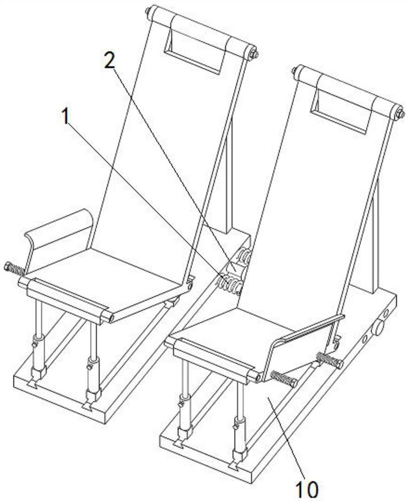
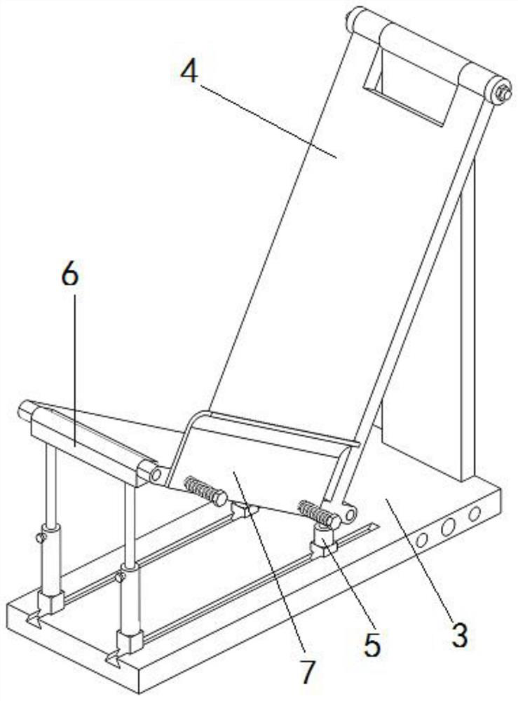
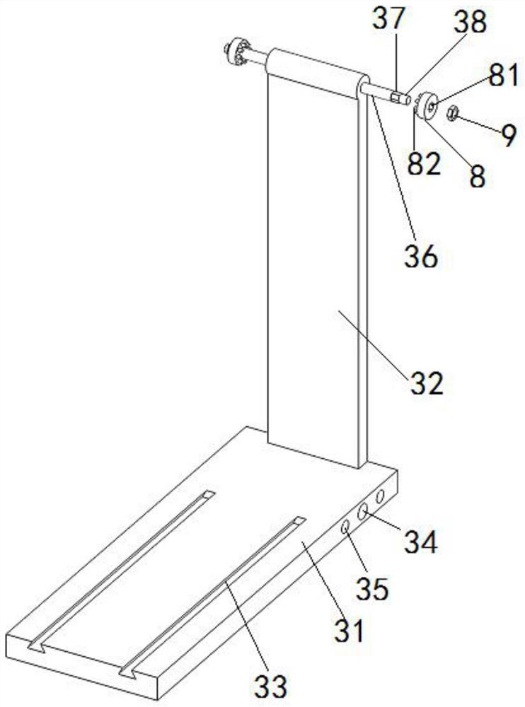
A-shaped frame positioning and mounting structure

A technology of positioning and installation, rack support, applied in the directions of transportation and packaging, furnace, charge manipulation, etc., can solve problems such as inconvenience

Active Publication Date: 2021-04-02
彩虹(合肥)液晶玻璃有限公司
View PDF5 Cites 0 Cited by
  • Summary
  • Abstract
  • Description
  • Claims
  • Application Information

AI Technical Summary

Problems solved by technology

Therefore, it is necessary to use corresponding A-frames for support and installation

Method used


Image

  • A-shaped frame positioning and mounting structure
  • A-shaped frame positioning and mounting structure
  • A-shaped frame positioning and mounting structure

Examples


Embodiment Construction

[0029] The following will clearly and completely describe the technical solutions in the embodiments of the present invention with reference to the accompanying drawings in the embodiments of the present invention. Obviously, the described embodiments are only some, not all, embodiments of the present invention. Based on the embodiments of the present invention, all other embodiments obtained by persons of ordinary skill in the art without creative efforts fall within the protection scope of the present invention.

[0030] In describing the present invention, it is to be understood that the terms "opening", "upper", "lower", "thickness", "top", "middle", "length", "inner", "surrounding" etc. Indicating orientation or positional relationship is only for the convenience of describing the present invention and simplifying the description, and does not indicate or imply that the components or elements referred to must have a specific orientation, be constructed and operated in a sp...


PUM


Abstract

The invention discloses an A-shaped frame positioning and mounting structure. The A-shaped frame positioning and mounting structure comprises two A-shaped frame supporting units which are symmetrically distributed, wherein the two A-shaped frame supporting units are connected through a telescopic mechanism, and two elastic limiting mechanisms are symmetrically mounted on the outer side of the telescopic mechanism. By means of scientific and reasonable structural design, according to different angle installation requirements of different glass substrates, adaptive adjustment can be conducted, the supporting width and angle can be adjusted in real time, safe clamping and fixing can be conducted, the production efficiency is improved, the application range is wide, and good practical and popularization value is achieved.

Description

technical field [0001] The invention belongs to the field of glass substrate manufacturing, in particular to an A-frame positioning and installation structure. Background technique [0002] In the automatic glass production process, the formed glass plate needs to be taken out by a mechanical and electrical device, then transported by a transmission device, and finally transported to an A-frame by a mechanical and electrical device for packaging. Therefore, it is necessary to use corresponding A-frames for supporting and installing different glass substrates, which brings some inconvenience to actual production. Contents of the invention [0003] The purpose of the present invention is to overcome the above problems in the prior art and provide an A-frame positioning and installation structure. [0004] In order to achieve the above-mentioned technical purpose and achieve the above-mentioned technical effect, the present invention is realized through the following technic...

Claims


Application Information

Patent Timeline
IPC IPC(8): B65G49/06
CPCB65G49/063
Inventor 陈伟吴国天纵亚汪路遥吴郑敏
Owner 彩虹(合肥)液晶玻璃有限公司
Why Eureka
Try Eureka