Rotary holding and clamping mechanism and rotary holding and clamping trolley

A technology of holding clamps and trolleys, applied in the direction of lifting devices, etc., can solve problems such as high labor intensity, smashed forklifts, damage to material molds, etc., and achieve the effects of low material cost, convenient loading and unloading, and large bearing capacity

Inactive Publication Date: 2021-04-02
西安创力源工业科技有限公司
View PDF10 Cites 3 Cited by
  • Summary
  • Abstract
  • Description
  • Claims
  • Application Information

AI Technical Summary

Problems solved by technology

[0003] The thickness of the plastic material is 12um-60um, and the width of the material roll is generally 600mm-1300mm. The raw material is a roll material, and the diameter of the material roll is generally Φ400mm-Φ800mm. The material film needs to be placed horizontally, and then put on the printing or laminating equipment. The current method of switching to horizontal placement is: before printing, the worker manually puts the vertically placed material film down on the forklift with a crowbar. After printing or laminating, the worker Then the horizontal material film is manually pushed up and erected on the material tray. This manual operation mode is labor-intensive and labor-intensive. It is also likely to cause adverse effects and safety consequences such as worker injury, material mold damage, and smashed forklifts.

Method used


Image

  • Rotary holding and clamping mechanism and rotary holding and clamping trolley
  • Rotary holding and clamping mechanism and rotary holding and clamping trolley

Examples


Embodiment 1

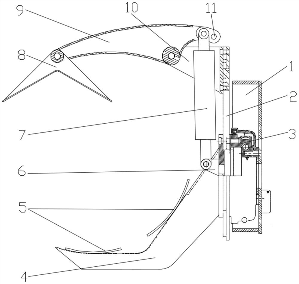
[0028] Such as figure 1 As shown, the rotating clamping mechanism provided in this embodiment includes a base 1 arranged on the body. The base 1 is provided with a turntable 2 and a rotating drive mechanism for driving the turntable 2 to rotate in a vertical plane. The turntable 2 is provided with There is a clamping mechanism, which includes a fixed arm 4 and a movable arm arranged on the turntable 2 facing each other; the cross section of the fixed arm 4 is "V"-shaped, and a free end of the fixed arm 4 is fixed to the turntable 2 connected, the open face of the fixed arm 4 faces the movable arm; it can be understood that the fixed arm 4 has a certain longitudinal width, and at least forms a line contact with the outer circumference of the coil, and the movable arm includes a hinge seat 10 fixedly connected with the turntable 2, the On the hinge base 10, a pivoted arm 9 is hinged, and the pivoted arm 9 is preferably arc-shaped. The end of the pivoted arm 9 away from the hinge...

Embodiment 2

[0033] Such as figure 1 As shown, the present embodiment is further optimized on the basis of embodiment 1, specifically:

[0034] A guard plate 5 with an arc-shaped cross section is fixed on both inner sides of the fixed arm 4 . Fixing the guard plate 5 with an arc-shaped cross-section on the two inner sides of the fixed arm 4 can effectively increase the contact area between the fixed arm 4 and the material roll, and further ensure the stability of the material roll clamp; especially after the material roll is stretched horizontally, The material roll is supported on the guard plate 5 of the fixed arm 4, which effectively increases the force-bearing area and makes the material roll horizontal support more stable, and the arc-shaped profiling guard plate plays a good role in limiting the material roll to avoid material Roll shifted or slipped during transfer.

[0035] One end of the pivoting arm 9 near the hinge base 10 is provided with a plurality of hinge holes 11 for hin...

Embodiment 3

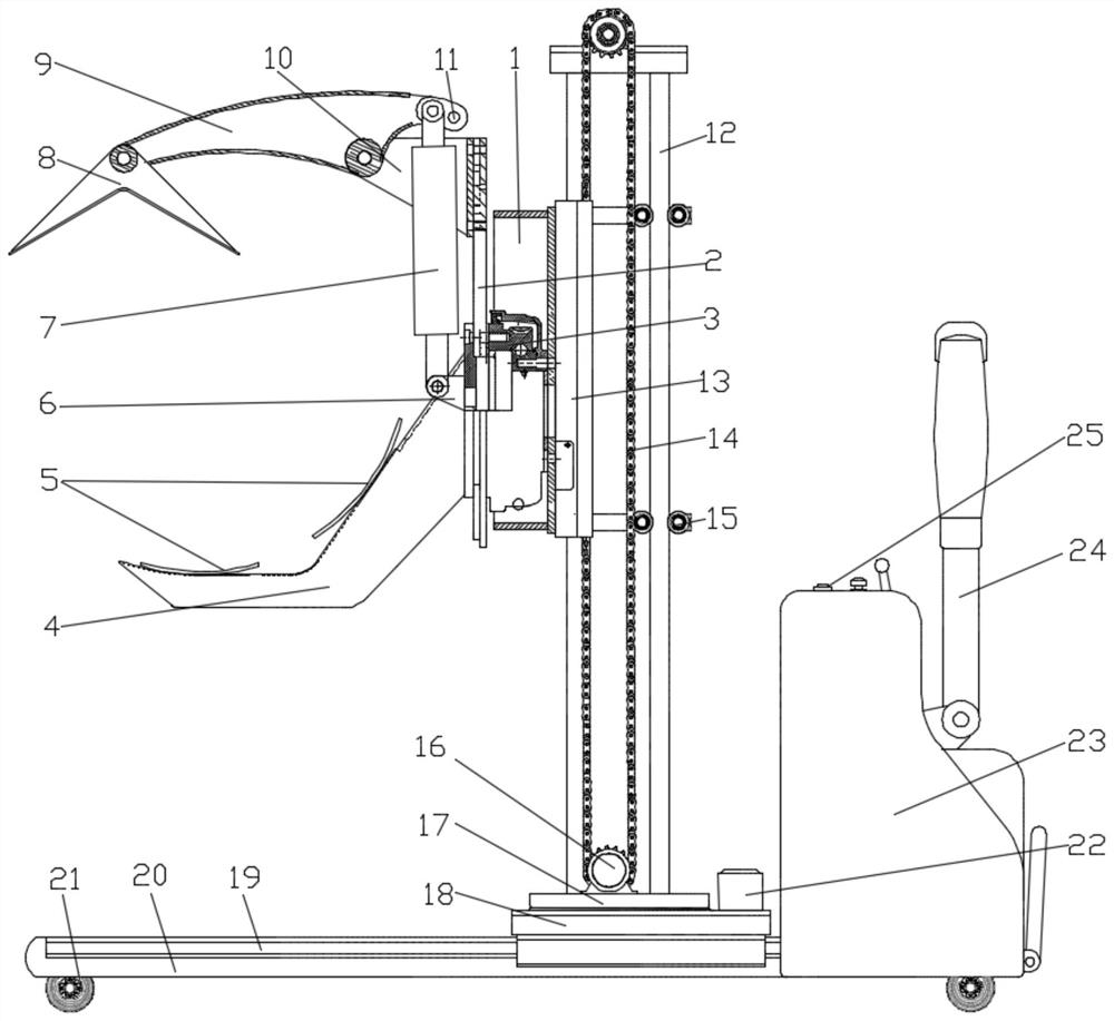
[0038] Such as figure 1 with figure 2 As shown, the rotary clamping trolley provided in this embodiment includes the rotary clamping mechanism described in Embodiment 2, and also includes a carrying trolley and a rotating lifting mechanism. The carrying trolley includes a vehicle frame 20 and a console 23 connected to the vehicle frame 20 , the bottom of the vehicle frame 20 and the console 23 are provided with casters 21; the vehicle frame 20 is provided with a chassis 18, the rotating lifting mechanism is arranged on the chassis 18, and the base 1 is fixed on the rotating lifting mechanism; The side of the console 23 away from the vehicle frame 20 is hinged with a push-pull rod 24, the inner cavity of the console 23 is provided with a drive module, and the console 23 is provided with a control panel 25, and the drive module is respectively and rotated The clamping mechanism and the rotating lifting mechanism are connected, and the driving module is electrically connected w...


PUM


Abstract

The invention discloses a rotary holding and clamping mechanism and a rotary holding and clamping trolley, and relates to the technical field of mechanical carrying. The problems of high labor intensity and potential safety hazards of manual carrying of material coils in plastic printing are solved. The rotary holding and clamping trolley comprises a frame and a chassis, a rotary lifting mechanismand a rotary holding and clamping mechanism are arranged on the chassis, and the rotary holding and clamping mechanism comprises a base. A rotary disc and a rotation driving mechanism for driving therotary disc to rotate in a vertical plane are arranged on the base, and a fixed arm and a movable arm are oppositely arranged on the rotary disc. The movable arm comprises a hinged support fixedly connected with the rotary disc, a rotary arm is hinged to the hinged support, a V-shaped clamping plate is hinged to the end, away from the hinged support, of the rotary arm, and a holding and clampingoil cylinder for driving the rotary arm to swing up and down around the hinged support is arranged on the rotary disc. According to the rotary holding and clamping mechanism and the rotary holding andclamping trolley, integrity is high, the structure is small, exquisite and compact, operation is simple and convenient, turning and moving of the rotary holding and clamping trolley are convenient, limitation from the operation site area is small, flexible operation in the small space is facilitated, and the application requirements of the printing clean workshop with the high clean requirement,small space and high load requirement are met.

Description

technical field [0001] The invention relates to the technical field of mechanical handling, in particular to a rotating holding mechanism and a rotating holding trolley. Background technique [0002] In the plastic flexible packaging industry, the raw materials are PET, BOPP, NY, PE, PVC and other plastic materials. After printing, compounding, slitting, bag making and other processes, the packaging of final products such as food, medicine, and daily chemical products is realized. The quality and quantity of the packaging are guaranteed, and the exquisite printing can enhance consumers' desire to buy. [0003] The thickness of the plastic material is 12um-60um, and the width of the material roll is generally 600mm-1300mm. The raw material is a roll material, and the diameter of the material roll is generally Φ400mm-Φ800mm. The material film needs to be placed horizontally, and then put on the printing or laminating equipment. The current method of switching to horizontal pl...

Claims


Application Information

Patent Timeline
Patent Type & Authority Applications(China)
IPC IPC(8): B66F9/06B66F9/18B66F9/20
CPCB66F9/06B66F9/18B66F9/20
Inventor 朱永波
Owner 西安创力源工业科技有限公司
Why Eureka
Try Eureka