Rotation drive device

A technology of a rotary drive device and a rotary mechanism, which is applied in metal material coating process, vacuum evaporation coating, coating, etc., can solve the problems of falling, insufficient adsorption force, substrate falling, etc., and achieve the effect of suppressing falling

Pending Publication Date: 2021-04-02
CANON TOKKI CORP
View PDF7 Cites 0 Cited by
  • Summary
  • Abstract
  • Description
  • Claims
  • Application Information

AI Technical Summary

Problems solved by technology

[0003] In such a device, for some reason, the substrate holder does not have sufficient suction force for the substrate, and the substrate may fall from the rotary drive device.
Moreover, even in the case of a structure in which the substrate is held on the substrate holder by the mechanical holder, there is a possibility that the substrate falls off from the holder and the substrate falls from the rotary drive device.

Method used


Image

  • Rotation drive device
  • Rotation drive device
  • Rotation drive device

Examples


Embodiment 1

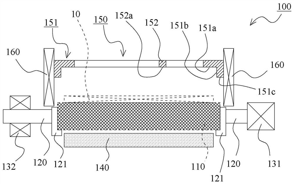
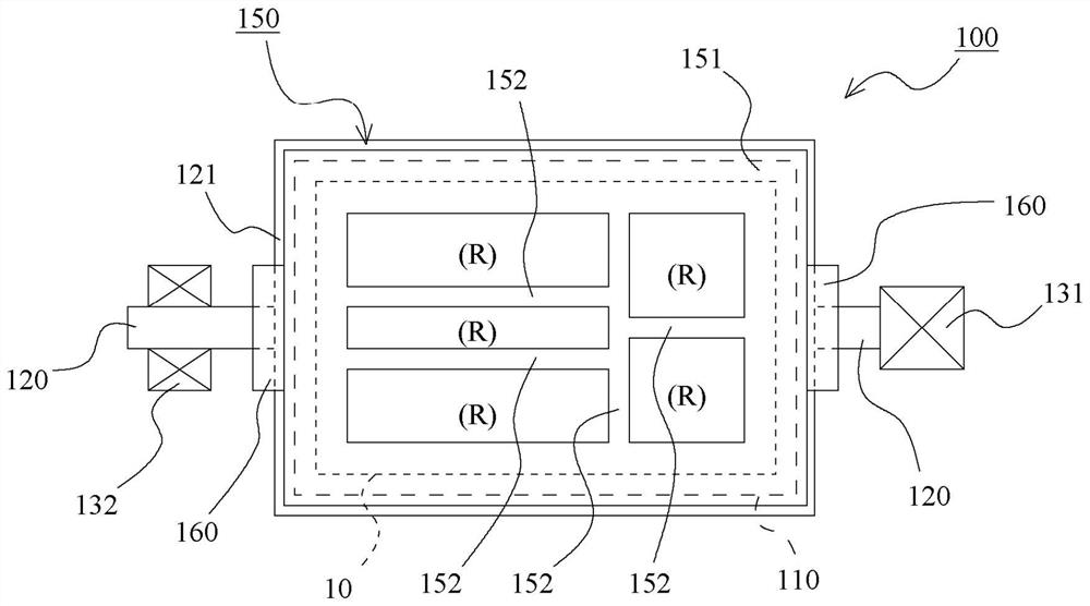
[0050] refer to Figure 1 to Figure 5 , the rotary driving device of Embodiment 1 of the present invention will be described. figure 1 It is a schematic configuration diagram of the rotary drive device according to the first embodiment of the present invention, and schematically shows the main configuration of the device when the device is viewed from the front. In addition, in order to facilitate understanding of the characteristics of each structure, the cross-section shows a part of the structure. figure 2 It is a schematic configuration diagram of the rotary drive device according to the first embodiment of the present invention, and schematically shows the main configuration of the device when the device is viewed from above. In addition, in order to facilitate the understanding of the arrangement relationship of the respective structures, some structures are shown in perspective with dotted lines. Moreover, in figure 1 and figure 2 In FIG. 2 , the carrier portion (...

Embodiment 2

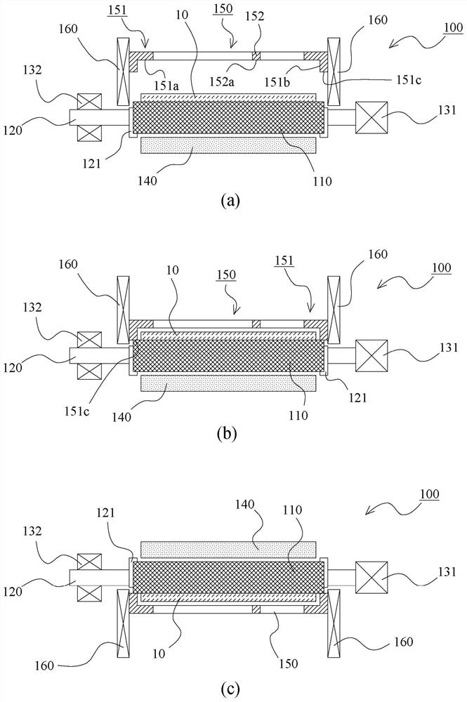
[0073] Figure 6 and Figure 7 Example 2 of the present invention is shown. In the above-mentioned first embodiment, the structure in which a gap is ensured over the entire area between the substrate and the second facing surface of the outer peripheral frame portion in the state where the substrate is held by the carrier portion is shown, but in this embodiment , shows a structure in which a part of the gap is removed. The other basic structures and functions are the same as those in Embodiment 1, and therefore the same structural parts are assigned the same reference numerals and their descriptions are omitted.

[0074] Figure 6 It is a schematic configuration diagram of the rotary drive device according to the second embodiment of the present invention, and schematically shows the main configuration of the device when the device is viewed from above. In addition, in order to facilitate understanding of the arrangement relationship of each structure, some structures are...


PUM


Abstract

The invention provides a rotation drive device which can restrain falling of a substrate. A rotation drive device (100) is provided with a rotation mechanism that rotates a carrier section (110) thatholds a substrate, and is characterized by being provided with: a housing (150) that has an outer peripheral frame section (151) provided along the outer periphery of the substrate (10) held by the carrier section (110), and that receives the substrate (10) when the substrate (10) falls down from the carrier section (110); and a reciprocating mechanism (160) that reciprocates the housing (150) soas to be able to change the distance between the facing surfaces of the housing (150) and the carrier section (110).

Description

technical field [0001] The invention relates to a rotary drive for rotating a substrate. Background technique [0002] In an apparatus for forming a film by vapor deposition, sputtering, etc., there is known a technique that includes a rotary drive device that attaches a substrate to a substrate having a function such as electrostatic clamping or adhesive clamping. In the state of the holder, the substrate is turned upside down together with the substrate holder (see Patent Document 1). [0003] In such an apparatus, the suction force of the substrate holder to the substrate becomes insufficient for some reason, and the substrate may fall from the rotational drive device. Furthermore, even in the case of adopting a structure in which the substrate is held by the substrate holder using the mechanical holder, there is a possibility that the substrate falls off the holder and the substrate falls from the rotational drive device. [0004] prior art literature [0005] patent ...

Claims


Application Information

Patent Timeline
Patent Type & Authority Applications(China)
IPC IPC(8): C23C14/50
CPCC23C14/505C23C14/34
Inventor 梅津琢治
Owner CANON TOKKI CORP
Why Eureka
Try Eureka