
Hydraulic anchoring test device and method

A test device, anchoring technology, applied in earthwork drilling, wellbore/well components, measurement, etc., can solve the problem of how to test the sealing performance, etc., to achieve easy implementation, promote more effective implementation, broad development space and application foreground effect

Pending Publication Date: 2021-04-02
中石化石油工程技术服务有限公司 +1
View PDF0 Cites 0 Cited by
  • Summary
  • Abstract
  • Description
  • Claims
  • Application Information

AI Technical Summary

Problems solved by technology

However, due to the absence of relevant test equipment, the difficulties in testing hydraulic anchors are: first, at a high temperature of 205°C and a high pressure difference of 105Mpa, while the hydraulic anchor claws are stuck on the casing wall, the hydraulic anchor is subjected to a bottom-up force. Lifting force, at this time, any test on the bearing capacity of the anchor fluke under the condition of a large load (99T); second, the sealing of the hydraulic anchor fluke under high temperature and high pressure at a high temperature of 205°C and a high pressure difference of 105Mpa How to test the performance

Method used


Image

  • Hydraulic anchoring test device and method

Examples


Embodiment Construction

[0031] The examples given below are specific descriptions of the present invention, and it is necessary to point out that the following examples are only used to further illustrate the present invention, and cannot be interpreted as limiting the protection scope of the present invention.

[0032] The descriptions referring to "first", "second", "third", "fourth", "fifth", etc. in the present invention are for descriptive purposes only, and shall not be construed as indicating or implying their relative importance or The number of technical characteristics indicated is implied. Thus, a feature defined as "first", "second", "third", "fourth", "fifth" may explicitly or implicitly include at least one of such feature.

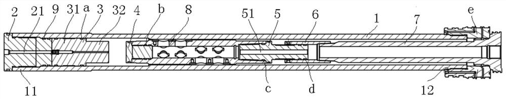
[0033] figure 1 An embodiment of a hydraulic anchoring test device among numerous embodiments of the present invention is shown as an example. The hydraulic anchoring test device includes a test casing 1 , a plug 2 , a piston 3 , a blocking member 4 , a telescopi...


PUM


Abstract

The invention discloses a hydraulic anchoring test device. The hydraulic anchoring test device comprises a test sleeve, a plug, a piston, a plugging piece, a connecting pipe, a telescopic pipe and a telescopic shaft, wherein the plug is used for plugging the first end of the test sleeve and comprises an injection hole for injecting pressurized fluid into the test sleeve, the piston is sleeved in the test sleeve and positioned between a hydraulic anchor and the plug, and is in sliding fit with the inner wall of the test sleeve, the plugging piece is used for plugging an opening of the end, facing the piston, of the hydraulic anchor, one end of the connecting pipe extends into the test sleeve, and the other end is used for being fixedly connected with a wellhead device, one end of the telescopic pipe fixedly communicates with the end, extending into the test sleeve, of the connecting pipe, the telescopic shaft is sleeved with the test sleeve and can at least move in the direction away from the piston in the axial direction of the test sleeve, an opening of a fluid channel at one end communicates with an opening of the end, opposite to the piston, of the hydraulic anchor, and the other end of the telescopic shaft is sleeved with the other end of the telescopic pipe and can slide towards the connecting pipe in the axial direction of the telescopic pipe. The hydraulic anchoring testdevice can realize anchoring force and sealing capability tests of the hydraulic anchor. The invention further discloses a hydraulic anchoring test method.

Description

technical field [0001] The invention relates to the field of oil well equipment testing, in particular to a hydraulic anchoring test device and method. Background technique [0002] The hydraulic anchor mainly consists of body, anchor claw, bead, high elastic spring, "O" type sealing ring and so on. The hydraulic anchor is lowered to the design position along with the tubing, and under the action of the pressure inside the tubing, the anchor fluke protrudes out of the body as the pressure gradually increases, so as to be stuck on the inner wall of the casing, preventing the tubing string from being displaced and failing during operation, thereby Play the role of anchoring the string. When unsealing, the pressure inside the oil pipe is released, and the anchor claw is retracted under the elastic force of the high-elasticity spring, so that the unsealing of the hydraulic anchor can be realized. Anchor the pipe string to avoid axial displacement of downhole tools. It is used...

Claims


Application Information

Patent Timeline
Patent Type & Authority Applications(China)
IPC IPC(8): E21B23/01E21B23/04E21B41/00E21B47/00
CPCE21B23/01E21B23/04E21B41/00E21B47/00
Inventor 李晖吕占春曹学军张朝举何世云周天春龙学任俊松杨桢李钦陈科铁忠银赵文雯傅伟唐祖兵罗斌丁跃
Owner 中石化石油工程技术服务有限公司
Learn More