Method for extracting goaf gas through top plate high-position comb-shaped drill holes

A high-level, comb-shaped technology, which is applied in the field of goaf gas extraction by high-level comb-shaped drilling on the roof, can solve problems such as potential safety hazards, unevenness, and waste of financial resources

Active Publication Date: 2021-04-02
SHANXI JINMEI GRP TECH RESEACH INST
View PDF5 Cites 0 Cited by
  • Summary
  • Abstract
  • Description
  • Claims
  • Application Information

AI Technical Summary

Problems solved by technology

With this extraction method, in order to ensure the effect of gas control in the goaf during the mining period, there must be stubble pressure in the high-level boreholes. Generally, the stubble pressure is within the range of 50-100m, which makes a large number of boreholes invalid and wastes a lot of manpower. , material resources, and financial resources; and affected by the "O" ring in the goaf, the gas in the goaf at the side of the goaf and the withdrawal channel cannot be solved by high-level drilling, and it is necessary to use technologies such as mid-level drilling and penetrating drilling. Increased construction difficulty for workers
At the same time, after the high-level drilling is cut off, a large amount of goaf gas remains in the cracks on the roof of the goaf, which not only causes energy waste, but also poses safety hazards
At present, in order to solve the hidden dangers of gas in old goafs and mine gas in old goafs, ground drainage wells are generally used to transform. This method not only wastes financial resources, but also covers a wide and uneven area, and the drainage effect is mediocre.

Method used


Image

  • Method for extracting goaf gas through top plate high-position comb-shaped drill holes
  • Method for extracting goaf gas through top plate high-position comb-shaped drill holes
  • Method for extracting goaf gas through top plate high-position comb-shaped drill holes

Examples


Embodiment Construction

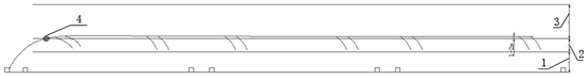
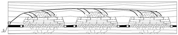
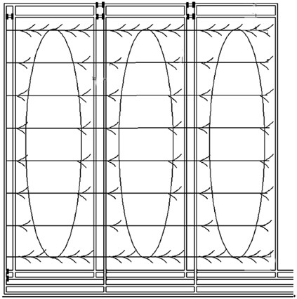
[0021] The layout of high-level comb-shaped drilling holes on the roof is as follows: Figure 1-Figure 3 As shown, this method mainly consists of the location of the drill hole (both sides of the roadway in the mining area or the roadway along the channel), the direction of the drill hole (along the stratum inclination), the layout of the horizontal section of the main hole (in the curved subsidence zone), the main hole Length (covering two or more coal mining faces), main hole spacing (60-80m), branch hole horizon (middle and lower part of coal seam roof fissure zone), branch hole spacing, branch hole length (covering both sides of the main hole 10- 20m range), the position of the end hole of the branch hole (located within the "O" ring) and other 9 parts.

[0022] The specific construction of high-level comb-shaped drilling on the roof is divided into the following steps, as follows: Figure 1-Figure 3 Shown:

[0023] In the first step, the borehole tracking design method ...


PUM


Abstract

The invention provides a method for extracting goaf gas through top plate high-position comb-shaped drill holes, and belongs to the field of gas extraction. The method aims at solving the problems ofgas in a goaf fissure zone of a stope face and gas in an old goaf after stoping is finished, and the use efficiency of the high-position drill holes is improved to the maximum extent. The high-position comb-shaped drill holes are formed in a coal face top plate along the stratum inclination on the two sides of a mining area roadway or a crossheading roadway, and main drill hole bodies are formed in a bent sinking zone of the coal seam top plate and located within the range of 1-2m above the junction of the coal seam top plate fissure zone and the bent sinking zone. According to the extractionmethod, the goaf gas in the stoping period of the coal face can be effectively extracted, the problem that the goaf gas in the final stoping period of the coal face rushes into the coal face can be effectively solved, especially, the extraction period of the top plate high-position drill holes can be greatly prolonged, the coal face is still kept intact after stoping is finished, continuous extraction of the gas in the old goaf is kept, a ground goaf extraction well is replaced, and the goaf gas extraction amount is increased.

Description

technical field [0001] The invention belongs to the technical field of gas drainage, and in particular relates to a method for gas drainage in a goaf through high-level comb-shaped holes on the roof. Background technique [0002] Coal is the main energy source in my country, accounting for about 70% of the primary energy structure. For a long time in the future, the status of coal as the main energy source will not change. The coal industry is an important basic industry related to the country's economic lifeline and energy security. With the development of the country, ensuring the safety of coal mines has become the focus of the country's increasing attention. At present, about 50% of coal mines in my country belong to "high gas mines" and "coal and gas outburst mines", and high-level drilling on the roof is generally used in China to drain gas from goafs. The high-level boreholes are all arranged along the coal seam inclination in the roof fissure zone of the coal mining...

Claims


Application Information

Patent Timeline
IPC IPC(8): E21F7/00E21B43/26
CPCE21F7/00E21B43/26
Inventor 张飞贺光会刘立州赵玮烨康锴王润超韩德虎赵学良王宁尚玮炜王莉罗华贵朱永辉
Owner SHANXI JINMEI GRP TECH RESEACH INST
Why Eureka
Try Eureka