Automobile asymmetric locking surface synchronizer assembly

An asymmetric, locking surface technology, used in clutches, brake types, components with teeth, etc., can solve problems such as insufficient shifting force, difficult operation, increased wear of shifting parts, etc., to achieve shifting operation. Convenience, easy shifting operation, and the effect of reducing impact force

Inactive Publication Date: 2021-04-02
浙江迅达工业科技股份有限公司
View PDF5 Cites 0 Cited by
  • Summary
  • Abstract
  • Description
  • Claims
  • Application Information

AI Technical Summary

Problems solved by technology

[0005] Aiming at the deficiencies of the prior art, the present invention provides an asymmetric locking surface synchronizer assembly for automobiles, which has the advantages of automatically adjusting the shifting force according to the actual situation and reducing the wear of the internal parts of the synchronizer, and solves the problem of the existing The activity performance of the existing synchronizer is relatively poor when shifting gears, which will make people more difficult when shifting gears. Not only that, the existing synchronizer will also make the impact force of the shift gear and the shift shaft when shifting gears Larger, this will make the wear of the internal parts of the synchronizer more serious, which will make the service life of the synchronizer shorter, and at the same time, people need to maintain and replace the auto parts frequently, which will increase people's life. The cost of maintaining a car, and the existing synchronizer may cause insufficient shifting force during use, which will also make the shifting operation more difficult, which in turn will increase the wear of the shifting parts

Method used


Image

  • Automobile asymmetric locking surface synchronizer assembly
  • Automobile asymmetric locking surface synchronizer assembly
  • Automobile asymmetric locking surface synchronizer assembly

Examples


Embodiment Construction

[0024] The following will clearly and completely describe the technical solutions in the embodiments of the present invention with reference to the accompanying drawings in the embodiments of the present invention. Obviously, the described embodiments are only some, not all, embodiments of the present invention. Based on the embodiments of the present invention, all other embodiments obtained by persons of ordinary skill in the art without making creative efforts belong to the protection scope of the present invention.

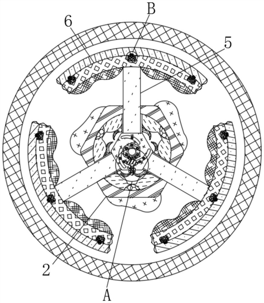
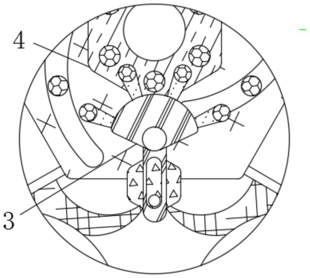
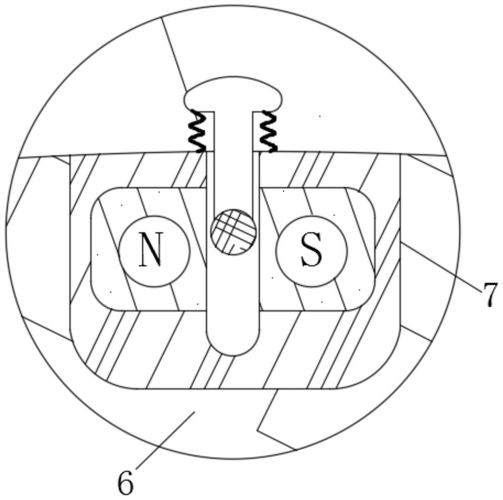
[0025] see Figure 1-5 , an asymmetrical locking surface synchronizer assembly for an automobile, comprising a shell 1, the shell 1 is movably connected to a shell 2 2 inside, the inside of the shell 2 2 is movably connected to a turntable assembly 3, and the outside of the turntable assembly 3 is movable Connected with a turntable 4, the outside of the turntable 4 is movably connected with a moving rod 5. The turntable assembly 3 is mainly composed of a turnt...


PUM


Abstract

The invention relates to the technical field of synchronizers, and discloses an automobile asymmetric locking surface synchronizer assembly. The automobile asymmetric locking surface synchronizer assembly comprises a first shell, a second shell is movably connected to the interior of the first shell, a rotating disc assembly is movably connected to the interior of the second shell, a rotating plate is movably connected to the exterior of the rotating disc assembly, and a moving rod is movably connected to the exterior of the rotating plate. A friction block is fixedly connected to the exteriorof the moving rod, and an electromagnetic assembly is fixedly connected to the interior of the friction block. Under the interaction of a rotating shell, a wire, a conductor, a fluid shell, an electro-rheological body, a rotating shaft, a movable block, a transmission shell, a convex block, a fixed ring, a coil and a rotating rod I, when the gear shifting force is insufficient, the automobile asymmetric locking surface synchronizer assembly can automatically provide the gear shifting force, so that the gear shifting operation of an automobile is simpler and more convenient, and people can shift gears more conveniently; and meanwhile, abrasion of internal parts during automobile gear shifting can be reduced, and then the automobile maintenance cost of people can be reduced.

Description

technical field [0001] The invention relates to the technical field of synchronizers, in particular to an asymmetric locking surface synchronizer assembly of an automobile. Background technique [0002] The synchronizer is a key component of a mechanical gear transmission automobile transmission, which undertakes the role of shifting and transmitting torque, but there are still many problems in the use of the current synchronizer, for example, the existing synchronizer is changing The activity performance when shifting gears is relatively poor, which will make people more difficult when shifting gears. Not only that, the existing synchronizer will also make the impact force of the shifting gear and the shifting shaft larger when shifting gears, so that It will make the wear of the internal parts of the synchronizer more serious, which will make the service life of the synchronizer shorter. At the same time, people need to maintain and replace the auto parts frequently, which...

Claims


Application Information

Patent Timeline
Patent Type & Authority Applications(China)
IPC IPC(8): F16D23/02F16D23/04F16D23/06F16D57/00F16D67/06F16H61/04
CPCF16D23/025F16D23/04F16D23/06F16D57/002F16D67/06F16D2023/0687F16H61/0403
Inventor 李贵铭罗仕祝刘忠云吴智渊
Owner 浙江迅达工业科技股份有限公司
Why Eureka
Try Eureka