Portable bamboo furniture panel
A portable and furniture technology, applied in the field of furniture, can solve the problem of inconvenient handling of bamboo furniture
- Summary
- Abstract
- Description
- Claims
- Application Information
AI Technical Summary
Problems solved by technology
Method used
Image

Examples
no. 1 example
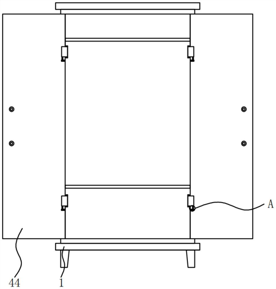
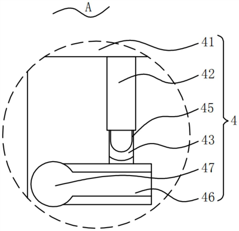
[0032] Please refer to figure 1 , figure 2 , image 3 , Figure 4 with Figure 5 ,in, figure 1 The structural representation of the first embodiment of the portable bamboo furniture panel provided by the present invention; figure 2 for figure 1 The enlarged view of A shown;
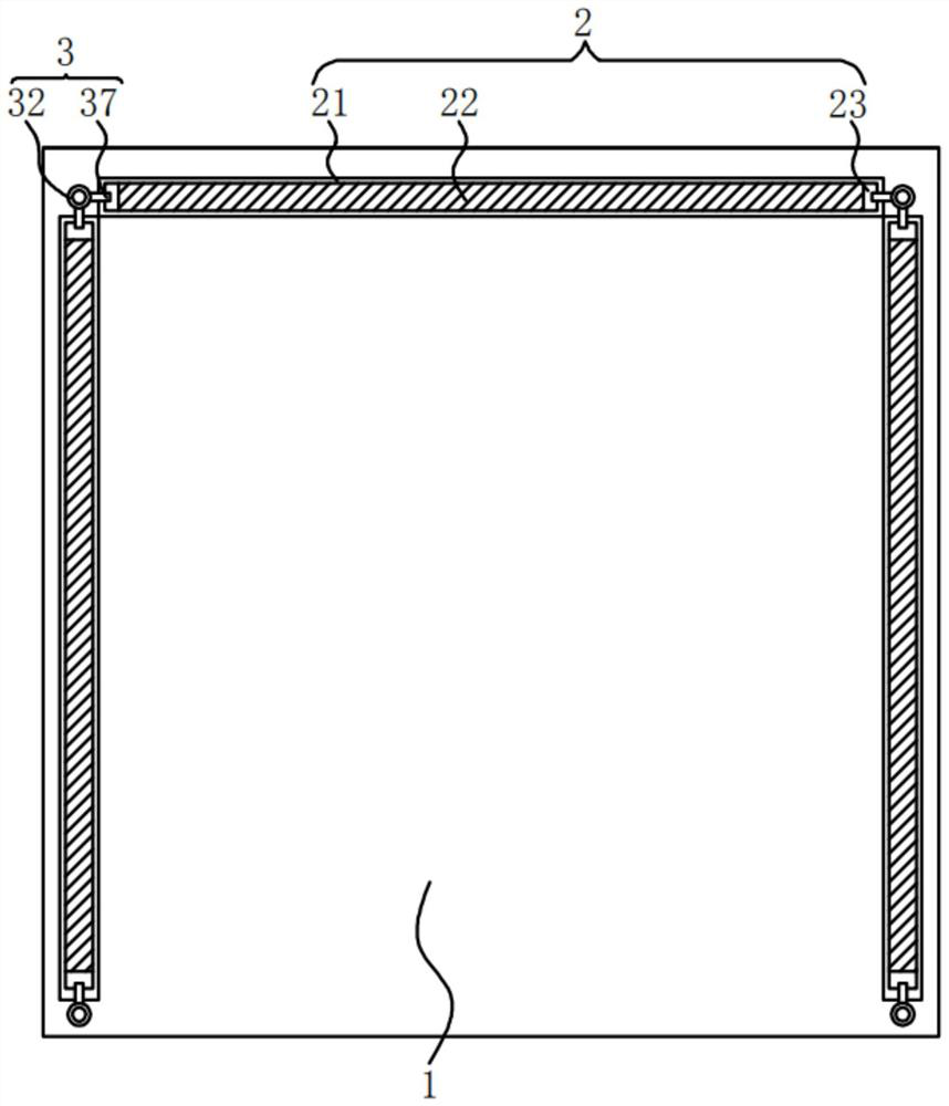
[0033] image 3 for figure 1 Top view of the substrate shown; Figure 4 for figure 1 Side view of the square bar shown; Figure 5 for Figure 4 A top view of the square rod shown. The portable bamboo furniture panel includes: a base plate 1; an installation assembly 2, the installation assembly 2 is fixed inside the base plate 1, the installation assembly 2 includes an installation groove 21, and an assembly plate 22 is slidably connected to the inside of the installation groove 21 , the assembly plate 22 is provided with a clamping groove 23; a clamping device 3, the clamping device 3 is fixed on the substrate 1, and the clamping device 3 includes a square rod 31, the square rod 31 One en...
no. 2 example
[0048] see Image 6 , Figure 7 , Figure 8 , Figure 9 , Figure 10 with Figure 11 , based on the portable bamboo furniture panel provided in the first embodiment of the present application, the second embodiment of the present application proposes another portable bamboo furniture panel. The second embodiment is only a preferred mode of the first embodiment, and the implementation of the second embodiment will not affect the independent implementation of the first embodiment.
[0049] Specifically, the difference of the portable bamboo furniture panel provided by the second embodiment of the present application is that the portable bamboo furniture panel also includes a rotating assembly 6, and the rotating assembly 6 is fixed on the bottom of the base plate 1, and the The rotating assembly 6 includes a fixed plate 61, on which a positive and negative threaded rod 62 is rotatably connected, and a threaded block 63 is threaded on the positive and negative threaded rod 6...
PUM
 Abstract
Description
Claims
Application Information
PatSnap Eureka turns technology decisions into work you can execute. Powered by our Innovation Knowledge Graph, it runs expert workflows across engineering, life sciences, materials and intellectual property. Get your review-ready output in minutes.


