Wastewater filtering and purifying device

A technology for filtering and purifying waste water, which is applied in the fields of filtration and separation, chemical instruments and methods, and separation methods, and can solve problems such as the inability to automatically change the filtration speed

Inactive Publication Date: 2021-04-06
HARBIN UNIV
View PDF1 Cites 5 Cited by
  • Summary
  • Abstract
  • Description
  • Claims
  • Application Information

AI Technical Summary

Problems solved by technology

[0002] For example, the publication number CN207713567U is a kind of waste water filtration and purification device, which belongs to the technical field of purification and cleaning. The bottom of the core is provided with a bottom filter, and the primary filter fiber ball is filled between the top filter and the bottom filter; one end of the se...

Method used


Image

  • Wastewater filtering and purifying device
  • Wastewater filtering and purifying device
  • Wastewater filtering and purifying device

Examples


specific Embodiment approach 1

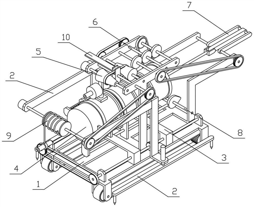
[0037] Combine below Figures 1 to 13 Describe this embodiment, a wastewater filtration and purification device, including a device bracket 1, a moving mechanism 2, a disassembly mechanism 3, a purification mechanism 4, a power mechanism 5, a transmission mechanism 6, an extrusion mechanism 7, a push mechanism 8, and a retractable mechanism 9 and the speed change mechanism 10, the left and right sides of the device support 1 are fixedly connected with the moving mechanism 2, the device support 1 is connected with the dismounting mechanism 3, the purification mechanism 4 is fixedly connected on the device support 1, and the purification mechanism 4 is fixedly connected on the disassembly On the mechanism 3, on the device bracket 1, a power mechanism 5 is connected, on the device bracket 1, a transmission mechanism 6 is rotatably connected, and the transmission mechanism 6 and the power mechanism 5 are connected in transmission, and the rear end of the device bracket 1 is rotatab...

specific Embodiment approach 2

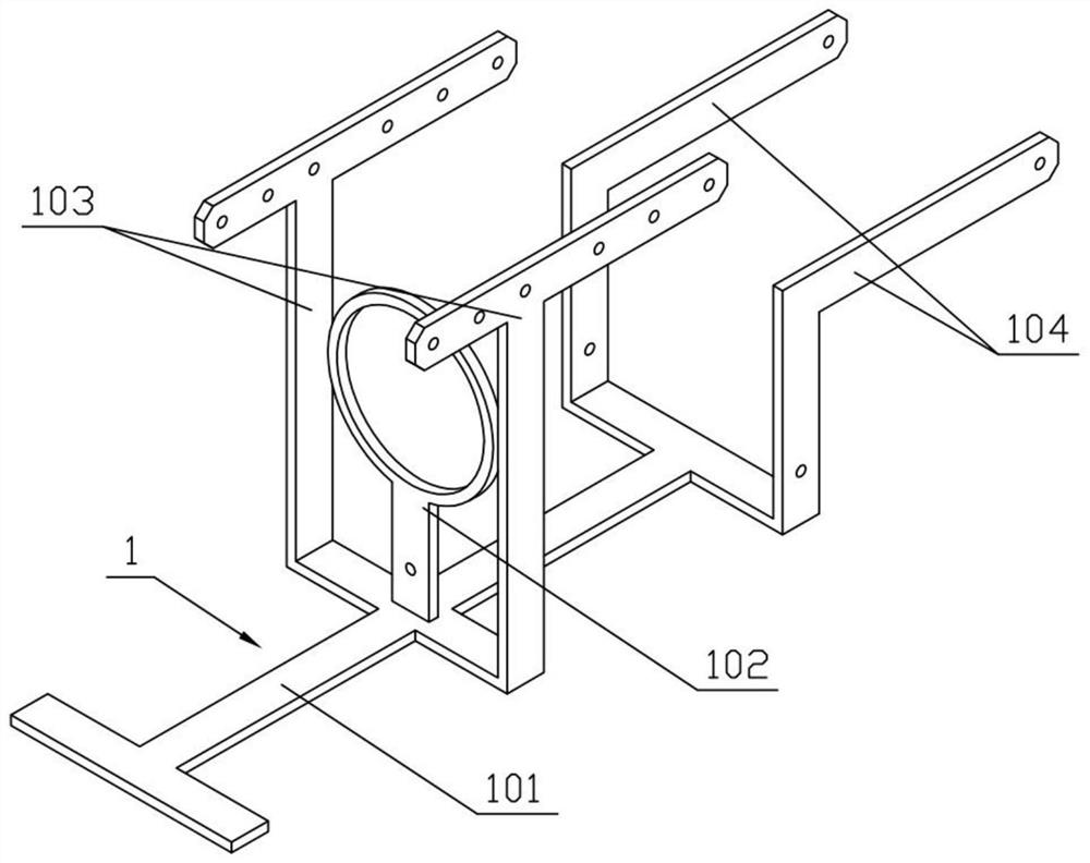
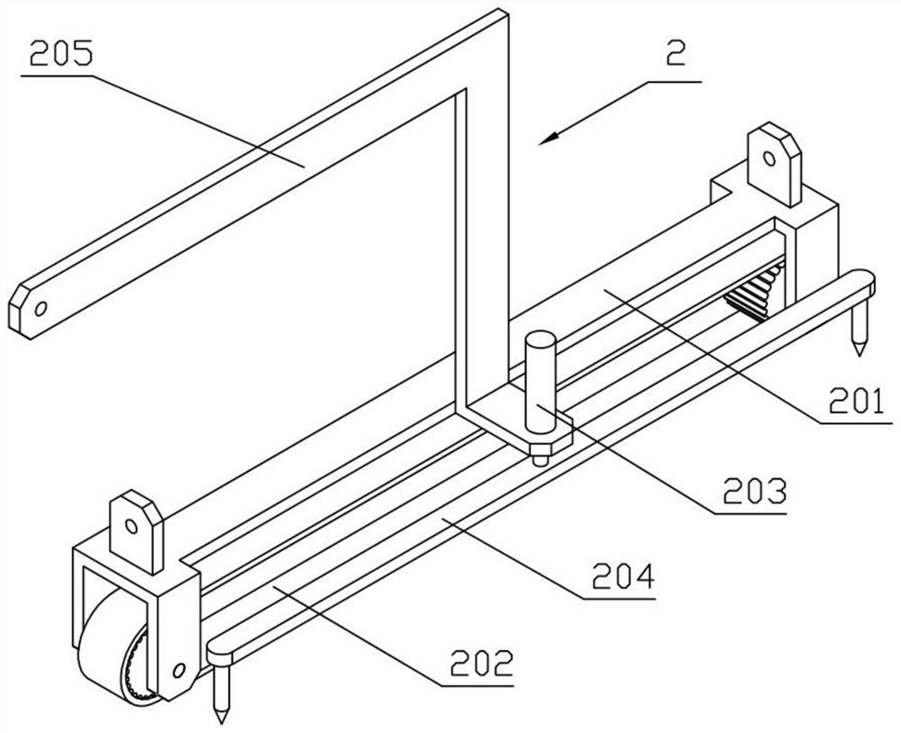
[0039] Combine below Figures 1 to 13 Describe this embodiment, this embodiment will further explain the first embodiment, the device bracket 1 includes a bottom bracket 101, a support ring I102, an installation side plate I103 and an installation side plate II104, and the middle part of the bottom bracket 101 is fixedly connected with a support ring I102 , the left and right sides of the bottom bracket 101 are fixedly connected with installation side panels I 103, the left and right sides of the rear end of the bottom bracket 101 are fixedly connected with installation side panels II 104, the moving mechanism 2 includes a moving bracket 201, a crawler mechanism 202, a telescopic mechanism 203, The positioning bottom plate 204 and the installation side plate III 205, the crawler mechanism 202 is connected to the mobile support 201, the telescopic mechanism 203 is fixedly connected to the mobile support 201, the telescopic end of the telescopic mechanism 203 is fixedly connected...

specific Embodiment approach 3

[0041] Combine below Figures 1 to 13 Describe this embodiment, this embodiment will further explain Embodiment 2. The disassembly mechanism 3 includes a disassembly screw 301, a disassembly bracket 302 and a support ring II 303. There are two disassembly screw 301, and two disassembly screw 301 The two dismantling screw rods 301 are respectively connected to the two movable brackets 201 in rotation, and the two dismantling screw rods 301 are connected with two dismantling brackets 302 by threads, and the two dismantling brackets 302 are fixedly connected with For the support ring II 303, the threads at both ends of the two dismantling screw rods 301 have opposite directions of rotation.


PUM


Abstract

The invention relates to a purifying device, in particular to a wastewater filtering and purifying device, which comprises a device support, a moving mechanism, a detaching mechanism, a purifying mechanism, a power mechanism, a transmission mechanism, an extruding mechanism, a pushing mechanism, a retracting and releasing mechanism and a speed changing mechanism. The transmission mechanism can be driven by the power mechanism to move, the transmission mechanism drives the extruding mechanism and the pushing mechanism to move, the extruding mechanism extrudes pollutants in the purification mechanism to separate insoluble pollutants from water, and when the pushing mechanism moves to the front end limit position, the pushing mechanism pushes the purification mechanism to be opened, so that the pollutants separated in the purification mechanism are discharged out of the purification mechanism. The retracting and releasing mechanism releases the water pumping pipeline to different depths, then the speed change mechanism is controlled to move, the speed change mechanism controls the output speed of the power mechanism, then the working speed of the extruding mechanism and the pushing mechanism is controlled, and therefore the use requirement for increasing insoluble substances in waste water in deep water is met.

Description

technical field [0001] The invention relates to a purification device, in particular to a waste water filtration and purification device. Background technique [0002] For example, the publication number CN207713567U is a kind of waste water filtration and purification device, which belongs to the technical field of purification and cleaning. The bottom of the core is provided with a bottom filter, and the primary filter fiber ball is filled between the top filter and the bottom filter; one end of the secondary filter is provided with a left filter, and the other end of the secondary filter is provided with a right filter. Net, between the filter screen on the left side and the filter screen on the right side is filled with secondary filter fiber balls; the shortcoming of this utility model is that the filtering speed cannot be automatically changed according to the use requirements. Contents of the invention [0003] The object of the present invention is to provide a wa...

Claims


Application Information

Patent Timeline
IPC IPC(8): B01D35/00B01D35/16
CPCB01D35/00B01D35/16
Inventor 刘嘉孔德勇刘充杜丛周彬
Owner HARBIN UNIV
Why Eureka
Try Eureka