Cooling furnace and material cooling method

A technology for cooling furnaces and materials, which is applied in the field of cooling furnaces and materials cooling, and can solve problems such as complex equipment structure, equipment failure, and low waste heat recovery

Active Publication Date: 2021-06-15
SGIS SONGSHAN CO LTD
View PDF10 Cites 0 Cited by
  • Summary
  • Abstract
  • Description
  • Claims
  • Application Information

AI Technical Summary

Problems solved by technology

However, the large air leakage rate of the annular cooler and the high power consumption of the fan lead to low waste heat recovery, and the equipment structure is complex. The annular cooler is in the process of continuous rotation, which is prone to equipment failure

Method used


Image

  • Cooling furnace and material cooling method
  • Cooling furnace and material cooling method
  • Cooling furnace and material cooling method

Examples


Embodiment Construction

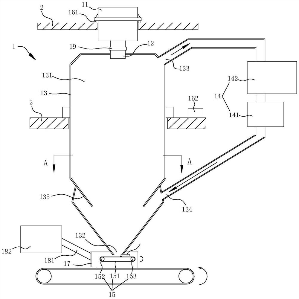
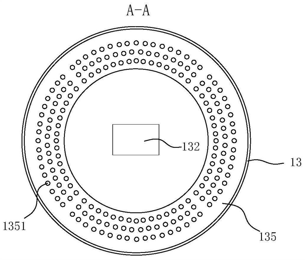
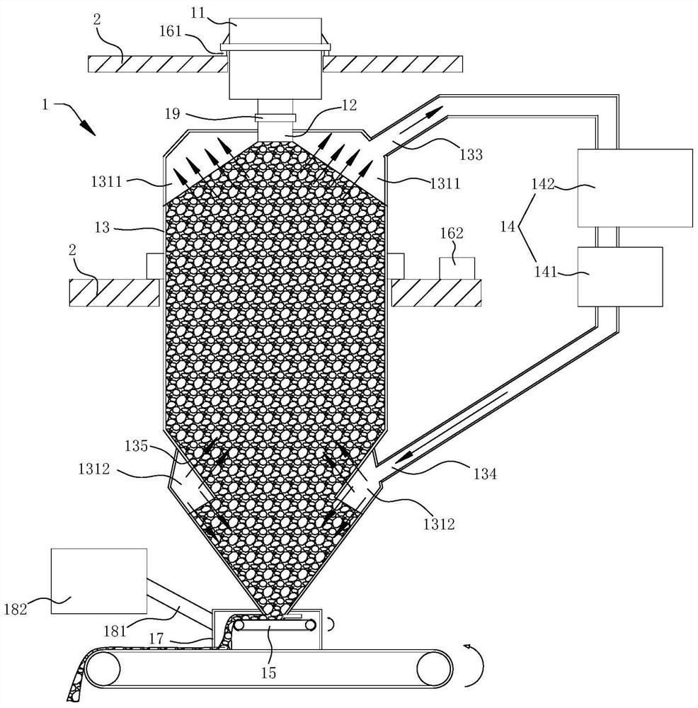
[0039] In order to make the technical problems solved by the present invention, the technical solutions adopted and the technical effects achieved clearer, the technical solutions of the embodiments of the present invention will be further described in detail below in conjunction with the accompanying drawings. Obviously, the described embodiments are only the technical solutions of the present invention. Some, but not all, embodiments. Based on the embodiments of the present invention, all other embodiments obtained by those skilled in the art without creative efforts fall within the protection scope of the present invention.

[0040] In the description of the present invention, unless otherwise clearly specified and limited, the terms "connected", "connected" and "fixed" should be understood in a broad sense, for example, it can be a fixed connection, a detachable connection, or an integrated ; It can be a mechanical connection or an electrical connection; it can be a direct...


PUM


Abstract

The invention relates to the technical field of cooling equipment, and particularly discloses a cooling furnace and a material cooling method. The cooling furnace comprises a storage bin, a feeding cylinder, a furnace body, a baffle, a waste heat recovery device and a discharging device, the feeding cylinder is arranged at the bottom of the storage bin, a containing cavity is formed in the furnace body, the feeding cylinder communicates with the storage bin and the containing cavity, the width of a cylinder opening of the feeding cylinder is smaller than the width of the bin wall of the storage bin and smaller than the width of the cavity wall of the containing cavity, the baffle is arranged at an angle relative to the side wall of the containing cavity, the baffle is located between the feeding cylinder and a discharging port of the containing cavity and inclines towards the discharging port, an air inlet and an air outlet are formed in the side wall of the containing cavity in a penetrating mode, the air inlet communicates with a first cavity and the waste heat recovery device, the air outlet communicates with a second cavity and the waste heat recovery device, a discharging device is arranged at the discharging port, and the discharging device is used for adjusting the material releasing speed of the discharging port. The cooling furnace is simple in structure, the equipment failure rate can be reduced, and the waste heat recovery efficiency is high.

Description

technical field [0001] The invention relates to the technical field of cooling equipment, in particular to a cooling furnace and a material cooling method. Background technique [0002] At present, in the material production operations of large and medium-sized iron and steel enterprises in my country, the sintering waste heat resources have not been recycled and utilized, resulting in waste of resources and serious environmental pollution. The waste heat resources in the sintering process are mainly composed of two parts: one is material sensible heat (such as sinter sensible heat), which accounts for about 70% of the total waste heat resources; the other part is sintering flue gas sensible heat, which accounts for about 30% of the total waste heat resources. %. In comparison, the amount of sensible heat of sinter is larger, and the quality of waste heat is higher. [0003] At present, the cooling machine in the domestic sintering production process usually uses a ring ty...

Claims


Application Information

Patent Timeline
Patent Type & Authority Applications(China)
IPC IPC(8): F27D15/02F27D3/00F27D17/00F27D19/00C22B1/26
CPCF27D15/0206F27D3/00F27D17/004F27D19/00C22B1/26F27D2019/0028Y02P10/25
Inventor 陈科李圭文郭震宇王勤福桂铁山张铁梁李国斌周清林陈创业师瑞红
Owner SGIS SONGSHAN CO LTD
Why Eureka
Try Eureka