
Cantilever type heading machine cutting mechanism adopting permanent magnet synchronous motor

A cantilever roadheader and permanent magnet synchronous technology, applied in cutting machinery, AC motor control, drive devices, etc., can solve the problems of poor applicability, low spray pressure, and unsatisfactory, and achieve good dust removal effect and high spray pressure , the effect of high work efficiency

Pending Publication Date: 2021-04-09
山西汾西华益实业有限公司
View PDF0 Cites 0 Cited by
  • Summary
  • Abstract
  • Description
  • Claims
  • Application Information

AI Technical Summary

Problems solved by technology

The structure of the two-stage planetary gear reducer is complex, and it takes a lot of manpower and material resources for maintenance in use. The mechanical efficiency η of the two-stage planetary gear reducer is about 0.88, which is relatively low; secondly, the speed of the three-phase asynchronous motor is constant and cannot be adjusted. The speed and applicability are poor; and the spray system of the cutting head of the cantilever roadheader has complex waterways, low spray pressure, easy leakage and unsatisfactory dust suppression effect

Method used


Image

  • Cantilever type heading machine cutting mechanism adopting permanent magnet synchronous motor
  • Cantilever type heading machine cutting mechanism adopting permanent magnet synchronous motor
  • Cantilever type heading machine cutting mechanism adopting permanent magnet synchronous motor

Examples


Embodiment Construction

[0022] In order to make the technical problems, technical solutions and beneficial effects to be solved by the present invention clearer, the present invention will be further described in detail below in conjunction with the accompanying drawings and embodiments. It should be understood that the specific embodiments described here are only used to explain the present invention, not to limit the present invention.

[0023] It should be noted that when an element is referred to as being “fixed” or “disposed on” another element, it may be directly on the other element or be indirectly on the other element. When an element is referred to as being "connected to" another element, it can be directly connected to the other element or indirectly connected to the other element.

[0024] It is to be understood that the terms "length", "width", "top", "bottom", "front", "rear", "left", "right", "vertical", "horizontal", "top", The orientation or positional relationship indicated by "bot...


PUM


Abstract

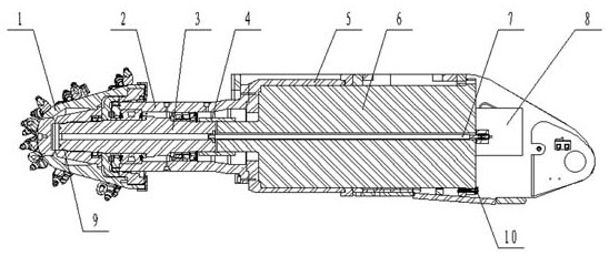
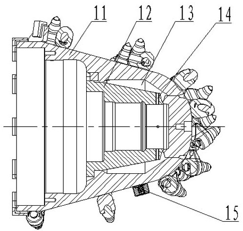
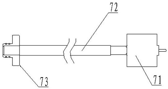
The invention discloses a cantilever type heading machine cutting mechanism adopting a permanent magnet synchronous motor. The method comprises the following steps that: a permanent magnet variable-frequency motor and a servo frequency converter are arranged in a motor box body, and are connected through a circuit; a cutting main shaft is connected with an output shaft of the motor through a spline sleeve; the cutting main shaft and the output shaft of the motor are hollow shafts; a cutting head is tightly connected with the cutting main shaft, and includes a cutting head body and an inner spline sleeve; a nozzle is arranged on the cutting head body; the inner spline sleeve is fixedly connected with the cutting head body; a water accommodating cavity is formed between the inner spline sleeve and the cutting head body, and communicates with the nozzle; a small hole is formed in the inner spline sleeve, and communicates with the water accommodating cavity; an inner spraying system is mounted in the hollow parts of the output shaft of the motor and the cutting main shaft; one end of a water pipe is tightly connected with the cutting main shaft, and the other end of the water pipe is tightly mounted on the motor. The cantilever type heading machine cutting mechanism can realize stepless speed adjustment of the cutting head, and is higher in working efficiency; and the spraying system is simple in water way, high in pressure and excellent in dust removing effect.

Description

technical field [0001] The invention belongs to the technical field of industrial and mining equipment, and in particular relates to a cutting mechanism of a cantilever type roadheader adopting a permanent magnet synchronous motor. Background technique [0002] With the high-speed growth of domestic urban road transportation, railways, highways, water conservancy, municipal engineering and other construction projects, my country's excavation machinery has also ushered in rapid development. my country's roadheader market has a promising prospect, and its market demand is huge. It is mainly divided into two development directions, coal mine roadheader and tunnel boring machine. In recent years, with the rapid development of my country's coal industry, the closely related coal machinery industry has also been paid more and more attention. Tunneling and mining are important production links in coal mine production. The country's policy is: pay equal attention to mining and exca...

Claims


Application Information

Patent Timeline
IPC IPC(8): E21C31/02E21C35/187E21C35/22H02P25/024H02P27/04
CPCE21C31/02E21C35/187E21C35/223H02P27/04H02P25/024
Inventor 浦国树张云峰
Owner 山西汾西华益实业有限公司
Learn More