Control device for hydraulic motor
A technology of hydraulic motor and control device, applied in the direction of fluid pressure actuation device, valve operation/release device, valve device, etc., can solve the problems of high production cost, affecting work efficiency, long time required, etc. The effect of low probability, simple troubleshooting and low production cost
- Summary
- Abstract
- Description
- Claims
- Application Information
AI Technical Summary
Problems solved by technology
Method used
Image
Examples
Embodiment 1
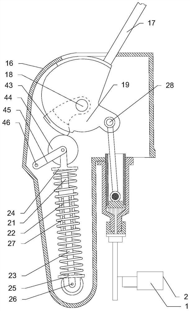
[0052] The present invention provides a hydraulic motor control device, including a hydraulic motor 1, the hydraulic motor 1 is connected with a manual speed regulating device, the manual speed regulating device is connected with a valve control device, and the valve control device is connected with the hydraulic motor 1 The oil inlet 2 of the hydraulic motor 1 is connected to the automatic speed regulating device, and the valve control device is manually controlled to adjust the size of the oil inlet 2 of the hydraulic motor 1, and adjust the amount of oil entering the hydraulic motor 1, thereby controlling the output speed of the hydraulic motor 1. Make adjustments.
[0053] Specifically, the manual speed regulating device includes a casing 16, and an operating handle 17 is arranged inside the casing 16, and the operating handle 17 and the casing 16 are pivotally connected by a pivot 18, and the operating handle 17 can rotate around the pivot 18. To rotate, the operating han...
Embodiment 2
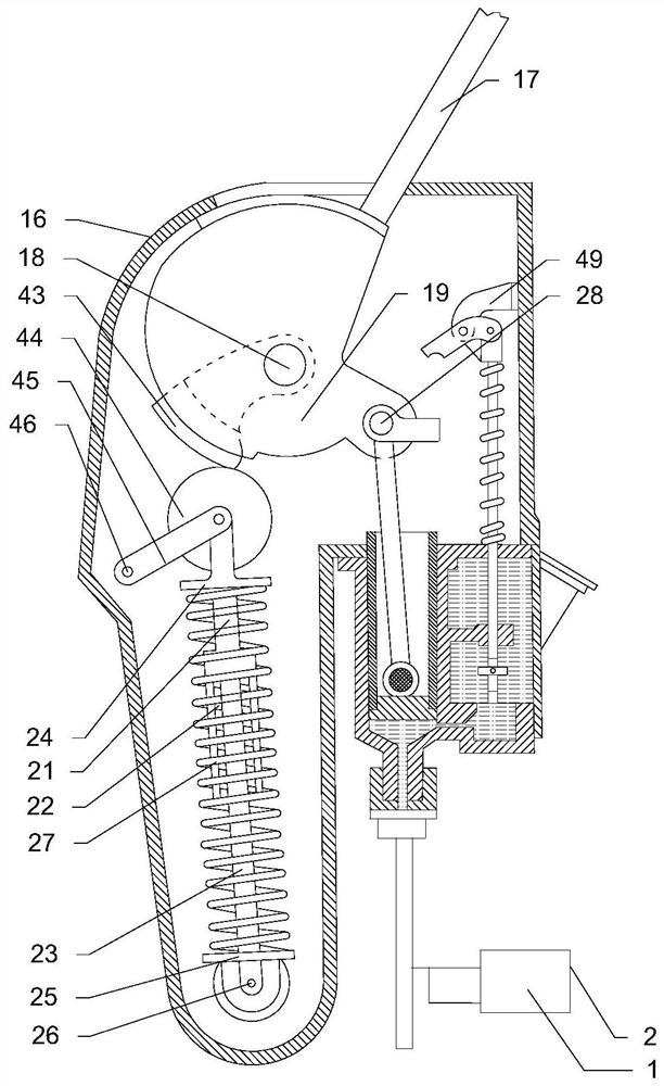
[0058] The difference between this embodiment and Embodiment 1 is that this embodiment also includes an oil replenishing device, and the oil replenishing device is connected with the manual speed regulating device to replenish oil to the manual speed regulating device.
[0059] Specifically, one end of the piston cylinder 32 is connected with an oil replenishing device, which can supplement the oil in the piston cylinder 1 32 while controlling the speed of the hydraulic motor 1 , without oiling the piston cylinder 1 32 separately. The replenishment is very convenient; specifically, the oil replenishing device includes an auxiliary storage 35, a passage 36 is provided between the auxiliary storage 35 and the piston cylinder one 32, and a valve two 37 is provided on the passage 36, and the Valve two 37 is connected with valve stem one 38, and valve stem one 38 drives valve two 37 to move, thereby opens or closes passage 36, realizes the supplement of oil; Said valve stem one 38 i...
Embodiment 3
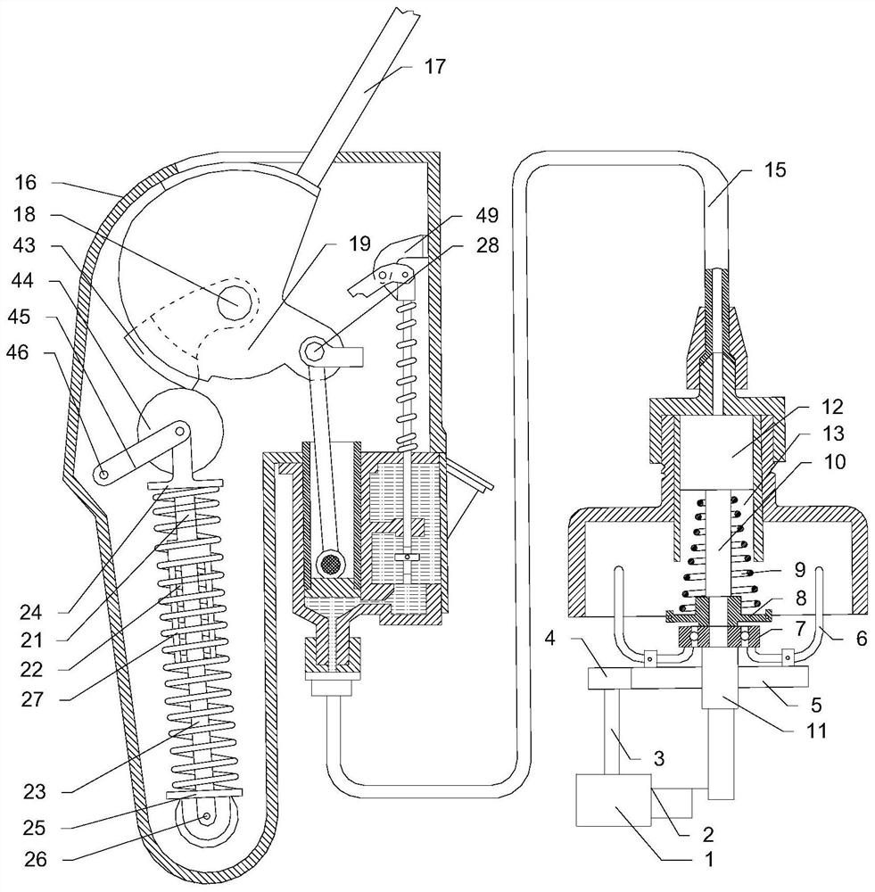
[0061] The difference between this embodiment and Embodiment 1 and Embodiment 2 is that this embodiment also includes an automatic speed regulating device, and the manual speed regulating device is connected to the automatic speed regulating device through a pipeline 15 .
[0062] Specifically, the automatic speed regulating device includes a connecting shaft 3, the connecting shaft 3 is connected with the output end of the hydraulic motor 1 through a structure such as a coupling, the connecting shaft 3 is connected with a gear one 4, and the gear one 4 is connected with a gear The two gears 5 are meshed, the gear two 5 is pivotally connected to the speed limiter 6, the speed limiter 6 is connected to the seat ring 7, the seat ring 7 is provided with a connection plate 8, and the top of the connection plate 8 is provided with Compression spring 9, the compression spring 9 is arranged on the outside of the valve stem 10, the valve stem 10 passes through the collar 11, the collar...
PUM
 Abstract
Description
Claims
Application Information
 - R&D
- Intellectual Property
- Life Sciences
- Materials
- Tech Scout
- Unparalleled Data Quality
- Higher Quality Content
- 60% Fewer Hallucinations
Browse by: Latest US Patents, China's latest patents, Technical Efficacy Thesaurus, Application Domain, Technology Topic, Popular Technical Reports.
© 2025 PatSnap. All rights reserved.Legal|Privacy policy|Modern Slavery Act Transparency Statement|Sitemap|About US| Contact US: help@patsnap.com


