

Visual sorting line for directionally feeding bottle garbage
A waste sorting technology, applied in sorting and other directions, can solve the problems of uneven feeding speed of vibrating feeder, inaccurate camera positioning, and misjudgment of jet valve group, so as to achieve good sorting effect and production efficiency. Fast, smooth and active feeding effect
- Summary
- Abstract
- Description
- Claims
- Application Information
AI Technical Summary
Problems solved by technology
Method used
Image

Examples
Embodiment Construction
[0048] The present invention will be described in further detail below in conjunction with the accompanying drawings. It should be noted that the words "front", "rear", "left", "right", "upper" and "lower" used in the following description refer to the directions in the drawings, and the words "inner" and "outer ” refer to directions towards or away from the geometric center of a particular part, respectively.
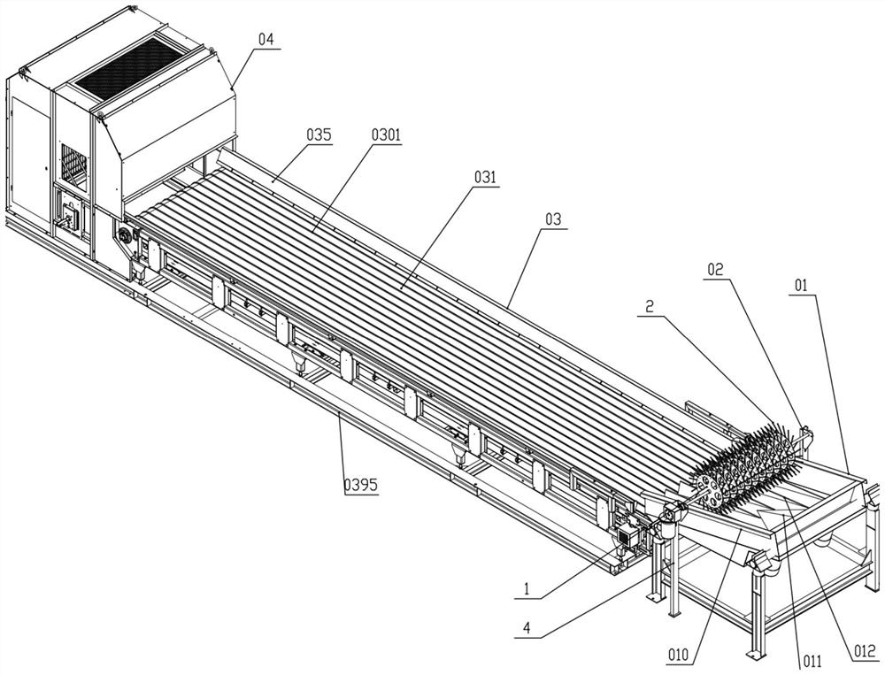
[0049] Figure 1 to Figure 12 It schematically shows a visual sorting line for directional feeding bottle waste according to an embodiment of the present invention. As shown in the figure, the device includes a directional vibrating feeder 01, a bottle pulling machine 02, a guide belt conveyor 03 and a high-speed jet optical separator 04;
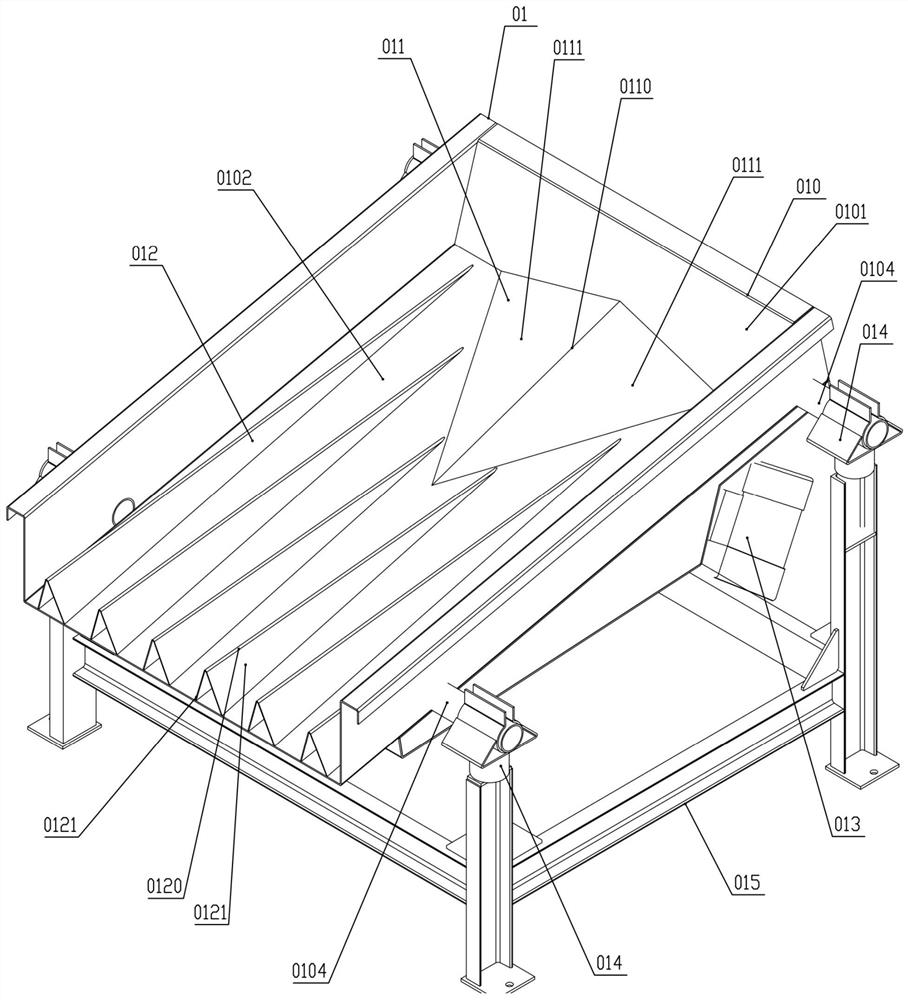
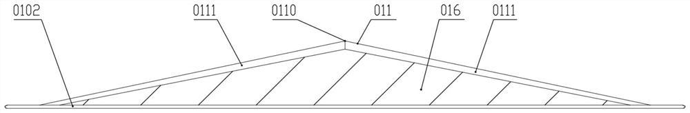
[0050] The directional vibrating feeder 01 includes a hopper 010 that slopes from upper right to lower left. A uniform material plate 011 is installed in the middle of the feed end of the lower chamber wall of the hopper 010, and ...
PUM
| Property | Measurement | Unit |
|---|---|---|
| Angle | aaaaa | aaaaa |
Abstract
Description
Claims
Application Information