Horizontal constant-speed material receiving device

A horizontal, material-distributing turntable technology, applied in thin material handling, transportation and packaging, transportation of filamentous materials, etc. Speed ​​and other issues to improve the efficiency of material collection and improve the effect of material collection

Active Publication Date: 2021-04-06
广州众山精密科技有限公司
View PDF13 Cites 2 Cited by
  • Summary
  • Abstract
  • Description
  • Claims
  • Application Information

AI Technical Summary

Problems solved by technology

[0005] How to solve the problem that the speed of receiving materials cannot be adjusted and controlled in the existing solution, resulting in poor receiving effect, and the problem that only one material can be collected, resulting in low receiving efficiency

Method used


Image

  • Horizontal constant-speed material receiving device
  • Horizontal constant-speed material receiving device
  • Horizontal constant-speed material receiving device

Examples


Embodiment 1

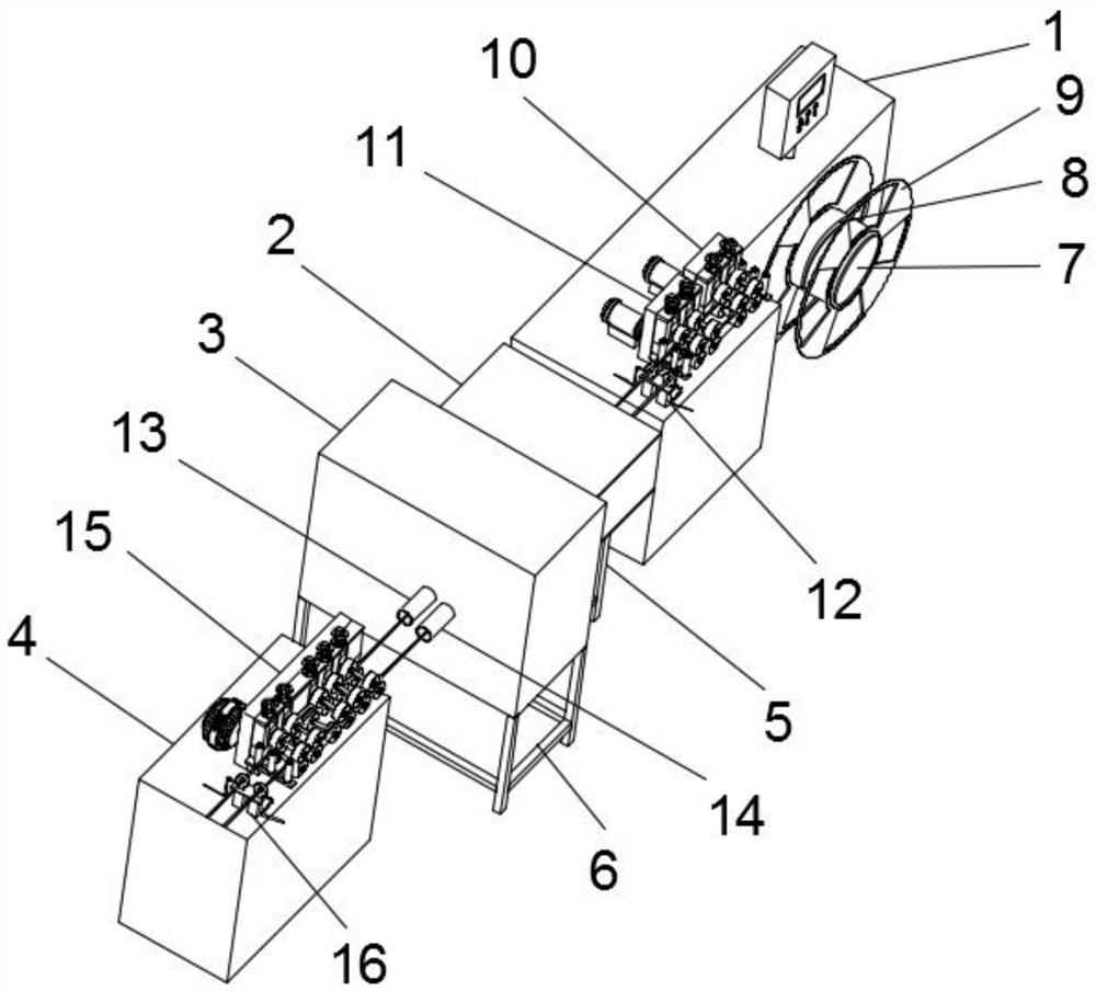
[0033] Such as Figure 1-5 As shown, a horizontal uniform speed receiving device includes a first support seat 1, a first connection seat 2, a second connection seat 3, a second support seat 4, a separation ring 8, a material distribution turntable 9, a first roller Sending mechanism 10, the second rolling mechanism 11, the first encoding mechanism 12, the tension mechanism 15 and the second encoding mechanism 16, the first connecting seat 2, the second connecting seat 3 and the second supporting seat 4 are all arranged on the second One side of a supporting seat 1, the second connecting seat 3 is located between the first connecting seat 2 and the second supporting seat 4, and the first connecting seat 2 is located between the first supporting seat 1 and the second connecting seat 3 Between, the front end of the first support base 1 is connected with a distributing rotating column 7 near the right side, and the distributing rotating disc 9 is installed at a position near the ...

Embodiment 2

[0042] The working method of the device comprises the following steps:

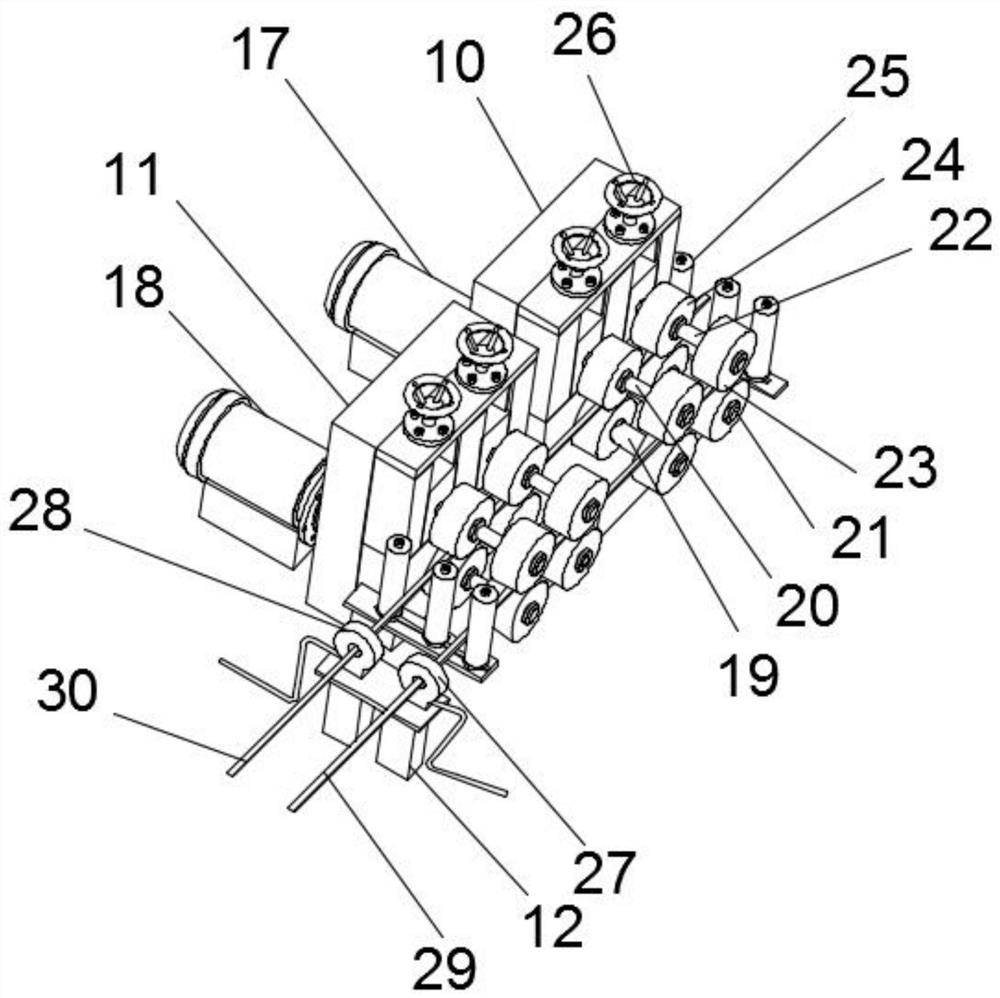
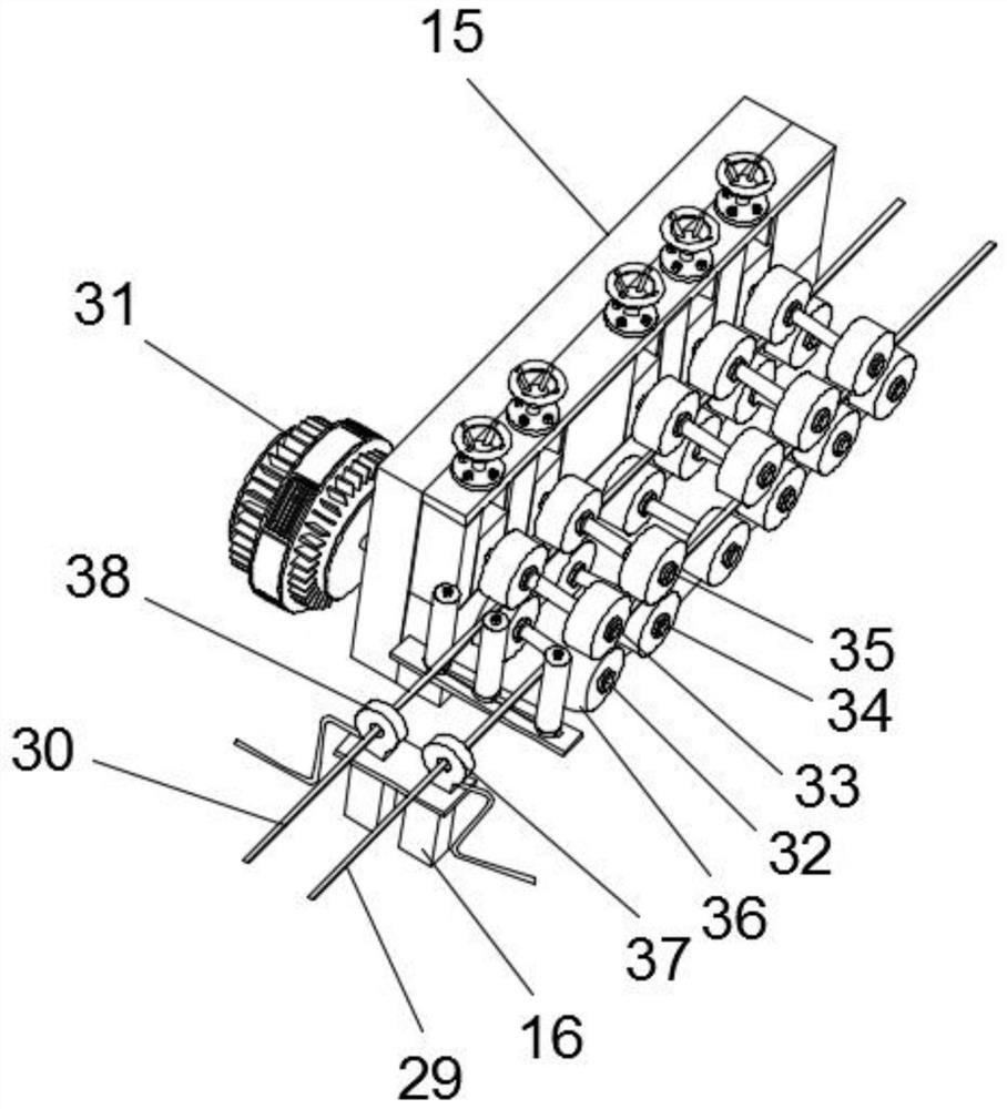
[0043] Step 1: Wrap the first metal strip 29 and the second metal strip 30 on both sides of the separating ring 8 on the distribution carousel 9 respectively, pass one end of the first metal strip 29 and the second metal strip 30 through several Between the first rollers 23 and between the second rollers 24, the first ring encoder 27 and the second ring encoder 28, the first connecting seat 2 and the second connecting seat 3, several first tension wheels Between 36 and the second tension wheel, and the third ring encoder 37 and the fourth ring encoder 38, the first metal strip 29 and the second metal strip 30 are rewound;

[0044] Step 2: Start the first drive motor 17, the second drive motor 18, the motor 31, the first hydraulic cylinder 40 and the second hydraulic cylinder 41, drive the first drive column 19 to rotate through the first drive motor 17, and pass through the first drive column 19 rotation...


PUM


Abstract

The invention discloses a horizontal constant-speed material receiving device which comprises a first supporting seat, a first connecting seat, a second connecting seat, a second supporting seat, a separating ring, a material distributing rotary disc, a first rolling mechanism, a second rolling mechanism, a first encoding mechanism, a tension mechanism and a second encoding mechanism. The first connecting seat, the second connecting seat and the second supporting seat are all arranged on one side of the first supporting seat, the second connecting seat is located between the first connecting seat and the second supporting seat, the first connecting seat is located between the first supporting seat and the second connecting seat, and the position, close to the right side, of the front end of the first supporting seat is connected with a material distributing rotary column. The material distributing rotary disc is installed at the position, close to the front portion, of the outer surface of the material distributing rotary column. According to various aspects, the problems that the material receiving effect is poor due to the fact that the material receiving speed cannot be adjusted and controlled and the material receiving efficiency is low due to the fact that only one material can be received in an existing scheme can be solved.

Description

technical field [0001] The invention relates to the technical field of metal receiving, in particular to a horizontal uniform-speed receiving device. Background technique [0002] At present, the metal processing market (CNC processing, etc.) has an increasing demand for metal profiles in order to improve processing efficiency, save costs, and reduce losses. ) requirements are getting higher and higher, which puts forward higher requirements for the control of metal materials in the process of processing. Annealing is an indispensable link. The quality of annealing is related to the surface quality, hardness stability and profile of stainless steel profiles Regarding the size of the residual stress, there are two commonly used feeding methods in the market at present: inverted feeding and horizontal feeding. [0003] The biggest problem of inverted type receiving is that there will be moving friction between the material and the receiving wheel to scratch the surface of the...

Claims


Application Information

Patent Timeline
IPC IPC(8): B65H51/08B65H54/547B65H54/70
CPCB65H51/08B65H54/547B65H54/70B65H2701/173
Inventor 朱华明刘孝东邱树生周毅军郑玉坤贺霞肖林平
Owner 广州众山精密科技有限公司
Why Eureka
Try Eureka