Movable directional transmission lifting platform
A lifting platform, mobile technology, applied in the direction of the lifting device, etc., can solve the problems of low telescopic efficiency and poor transmission effect of the lifting device, and achieve the effects of simple structure, enhanced flexion and extension, and reduced cost
- Summary
- Abstract
- Description
- Claims
- Application Information
AI Technical Summary
Problems solved by technology
Method used
Image

Examples
Embodiment Construction
[0034] The present invention will be described in detail below in conjunction with the accompanying drawings and specific embodiments.
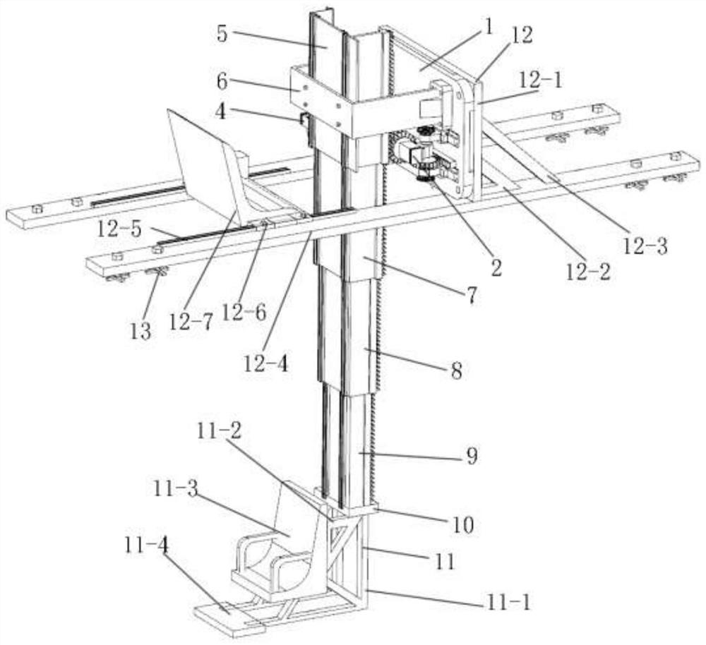
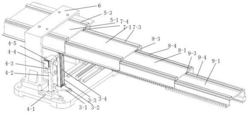
[0035] The present invention is a mobile directional transmission lifting platform, such as figure 1 and Figure 4 As shown, it includes a machine base 1, one side of the machine base 1 is connected with a support chassis 12, and the other side of the machine base 1 is respectively provided with a support frame 6, an automatic screw box 3, a screw positioning device 4, and a driving device 2. The screw box 3 is connected with the screw positioning device 4, the support frame 6 is connected with the flexion and extension device I5, and one end of the flexion and extension device I5 is connected with the flexion and extension device II7, the flexion and extension device III8, the flexion and extension device IV9, the connecting block 10, and the connecting block 10 is connected with a lowering seat 11.
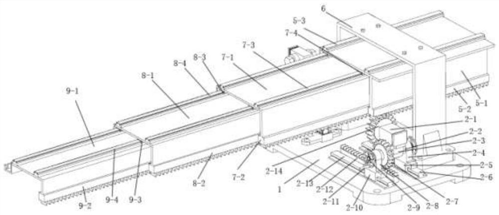
[0036] Such as Figure 7 As shown, th...
PUM
 Abstract
Description
Claims
Application Information
 - Generate Ideas
- Intellectual Property
- Life Sciences
- Materials
- Tech Scout
- Unparalleled Data Quality
- Higher Quality Content
- 60% Fewer Hallucinations
Browse by: Latest US Patents, China's latest patents, Technical Efficacy Thesaurus, Application Domain, Technology Topic, Popular Technical Reports.
© 2025 PatSnap. All rights reserved.Legal|Privacy policy|Modern Slavery Act Transparency Statement|Sitemap|About US| Contact US: help@patsnap.com