Power distribution cabinet based on substation power transmission

A power transmission and substation technology, applied in the substation/distribution device casing, substation/switchgear cooling/ventilation, substation/switch layout details, etc. and other problems, to achieve the effect of easy use, reducing the space occupied by the cabinet, and improving the range of activities

Active Publication Date: 2021-04-06
南京德嘉电气成套设备有限公司
View PDF4 Cites 2 Cited by
  • Summary
  • Abstract
  • Description
  • Claims
  • Application Information

AI Technical Summary

Problems solved by technology

[0002] The substation refers to the place where the voltage and current are transformed, received and distributed in the power system. The substation in the power plant is a step-up substation. Its function is to boost the power generated by the generator and feed it to the high-voltage power grid. The power distribution cabinet is divided into power distribution cabinet, lighting distribution cabinet and metering cabinet. The power distribution cabinet is the final equipment of the power distribution system. The power distribution cabinet is the general name of the motor control center. In rare occasions, the power distribution cabinet distributes the power of a certain circuit of the upper-level power distribution equipment to the nearby load. The structure of the existing power distribution cabinet is extremely complicated. After the cabinet door on the cabinet is opened, the total occupied space of the cabinet Larger, causing a lot of inconvenience in use

Method used


Image

  • Power distribution cabinet based on substation power transmission
  • Power distribution cabinet based on substation power transmission
  • Power distribution cabinet based on substation power transmission

Examples


Embodiment Construction

[0025] The following will clearly and completely describe the technical solutions in the embodiments of the present invention with reference to the accompanying drawings in the embodiments of the present invention. Obviously, the described embodiments are only some, not all, embodiments of the present invention. Based on the embodiments of the present invention, all other embodiments obtained by persons of ordinary skill in the art without making creative efforts belong to the protection scope of the present invention.

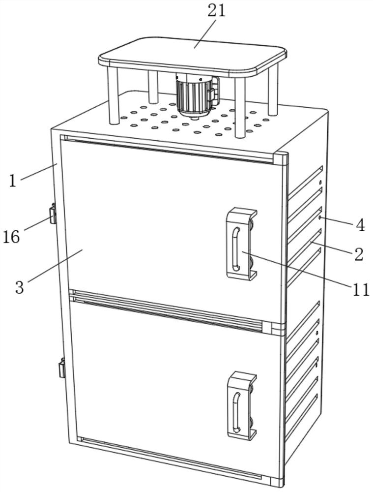
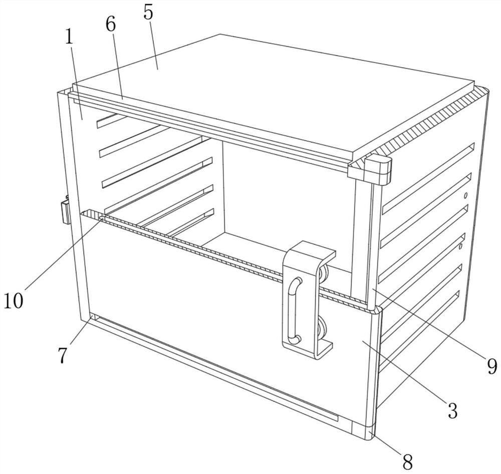
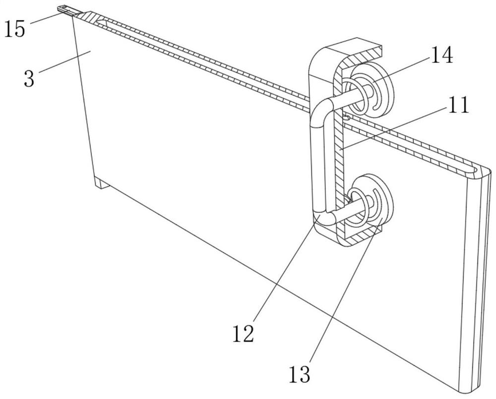
[0026] see Figure 1-5, the present invention provides a technical solution: a power distribution cabinet based on substation power transmission, including a cabinet body 1, the left side and the right side of the cabinet body 1 are provided with ventilation openings 2, through which the ventilation openings 2 , so that the cabinet 1 has a ventilation function, so that the electrical components inside the cabinet 1 are easy to dissipate heat, thereby improving...


PUM


Abstract

The invention relates to the technical field of substation equipment, and discloses a power distribution cabinet based on substation power transmission. The power distribution cabinet comprises a cabinet body, ventilation openings are formed in the left side surface and the right side surface of the cabinet body, cabinet doors are arranged at the top and the bottom of the front surface of the cabinet body, and locking grooves are formed in the top and the bottom of the left side surface and the right side surface of the cabinet body. A partition plate is fixedly connected to the middle of the inner wall of the cabinet body. According to the power distribution cabinet based on transformer substation power transmission, stabilizing sliding grooves are slidably connected with the outer surfaces of stabilizing rods, so that the cabinet doors have a rotating function, the cabinet doors can be rotated to the right side face of the cabinet body, the space occupied by the cabinet body can be reduced, and obstacles are reduced when a worker maintains electrical apparatus elements in the cabinet body, the movement scope of workers is improved, and thus the maintainence efficiency of the workers is improved; and meanwhile, the power distribution cabinet is simple and convenient in structure and convenient for the working personnel to use, and the situation that the operation is strenuous is avoided.

Description

technical field [0001] The invention relates to the technical field of substation equipment, in particular to a power distribution cabinet for power transmission based on a substation. Background technique [0002] The substation refers to the place where the voltage and current are transformed, received and distributed in the power system. The substation in the power plant is a step-up substation. Its function is to boost the power generated by the generator and feed it to the high-voltage power grid. The power distribution cabinet is divided into power distribution cabinet, lighting distribution cabinet and metering cabinet. The power distribution cabinet is the final equipment of the power distribution system. The power distribution cabinet is the general name of the motor control center. In rare occasions, the power distribution cabinet distributes the power of a certain circuit of the upper-level power distribution equipment to the nearby load. The structure of the exis...

Claims


Application Information

Patent Timeline
Patent Type & Authority Applications(China)
IPC IPC(8): H02B1/30H02B1/56
CPCH02B1/30H02B1/565
Inventor 吕佳
Owner 南京德嘉电气成套设备有限公司
Why Eureka
Try Eureka