Electric motors, powertrains and equipment

A technology of oil passages and nozzles, applied in the field of motors, can solve the problems of poor heat dissipation of the stator core and coil windings, and excessive temperature of the coil windings.

Active Publication Date: 2022-05-13
HUAWEI DIGITAL POWER TECH CO LTD
View PDF0 Cites 0 Cited by
  • Summary
  • Abstract
  • Description
  • Claims
  • Application Information

AI Technical Summary

Problems solved by technology

[0005] The embodiment of the present application provides a motor, power assembly and equipment, which achieves the purpose of double-layer oil passage on the outer surface of the stator core and the root of the coil slot of the stator core, and ensures effective cooling of the stator core and coil windings , so as to ensure the heat dissipation requirements of the motor under low-speed, high-torque and high-speed conditions, and solve the problem of poor heat dissipation of the stator core and coil winding in the existing motor, which causes the coil winding of the motor to be easily damaged under low-speed, high-torque and high-speed conditions overheating problem

Method used


Image

  • Electric motors, powertrains and equipment
  • Electric motors, powertrains and equipment
  • Electric motors, powertrains and equipment

Examples


Embodiment 1

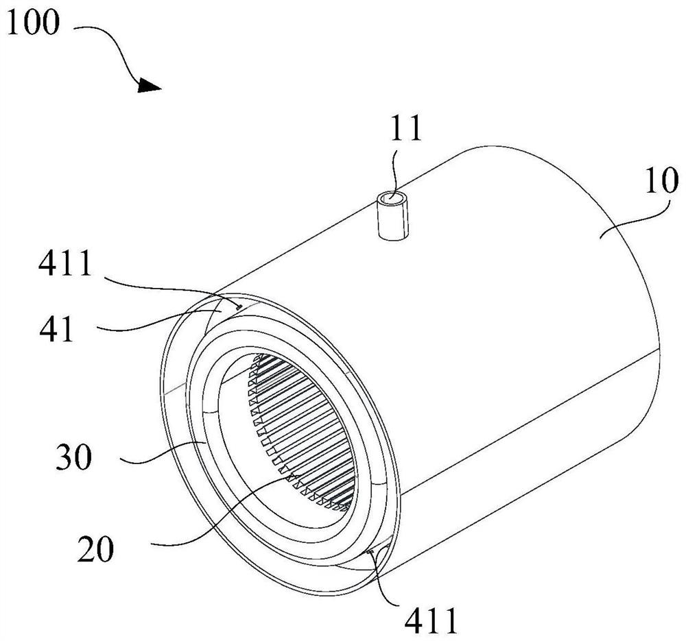
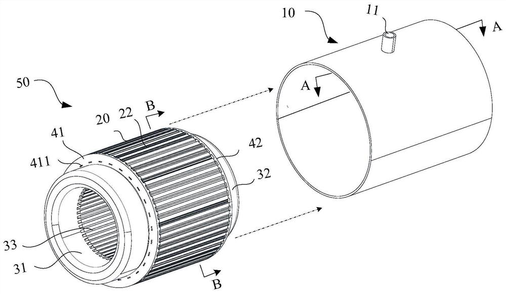
[0184] In the embodiment of this application, see Figure 17 As shown, the first end cover 41 at least includes: a first annular end plate 401, and a third oil passage 103 is formed between the first annular end plate 401 and one end surface of the stator core 20 (see the following Figure 25 ). see Figure 21 The second end cover 42 shown at least includes: a second annular end plate 402, and a fourth oil passage 104 is formed between the second annular end plate 402 and the other end surface of the stator core 20 (see the following Figure 25 ).

[0185] see Figure 17 As shown, a plurality of first nozzles 411 are arranged at intervals along the circumferential direction of the first annular end plate 401, see Figure 20 As shown, a plurality of second nozzles 421 are arranged at intervals along the circumferential direction of the second annular end plate 402 . In this way, the cooling oil ejected from a plurality of first nozzles 411 can evenly dissipate heat in the ...

Embodiment 2

[0196] The difference between the embodiment of the present application and the first embodiment above is: in the embodiment of the present application, see Figure 27 with Figure 28A As shown, the first nozzle 411 is a circular nozzle, see Figure 28B As shown, the second nozzle 421 is a circular nozzle, see Figure 29 As shown, a plurality of first nozzles 411 are evenly spaced in the circumferential direction. see Figure 30 As shown, the first nozzle 411 is opened on the first recess 417 of the first blocking block 416 , and the first nozzle 411 is close to the outer ring of the first end cap 41 .

[0197] In the embodiment of the present application, when the first nozzle 411 and the second nozzle 421 are set as circular nozzles, under the same oil pressure, the circular nozzles can make the cooling oil spray to the two sides of the coil winding 30 at a faster speed. on one end.

[0198] In the embodiment of the present application, the nozzle is an inclined nozzle ...

Embodiment 3

[0202] The difference between the embodiment of the present application and the above two embodiments is: in the embodiment of the present application, the first nozzle 411 and the second nozzle 421 can be arranged face to face with the first end 31 and the second end 32, Figure 35 for Figure 34 The perspective view of the stator after the middle housing 10 is removed, see Figure 35 As shown, the first end cover 41 also includes: a first extension plate 403 protruding axially and connected to the outer edge of the first annular end plate 401 , that is, one end of the first extension plate 403 is connected to the first annular end plate 401 The outer edges of the first extension plate 403 protrude outward along the axial direction of the stator core 20 . The second end cover 42 also includes: a second extension plate 404 protruding axially and connected to the outer edge of the second annular end plate 402 , that is, one end of the second extension plate 404 is connected to...


PUM


Abstract

Embodiments of the present application provide an electric motor, a power assembly, and equipment. By forming a plurality of first oil passages between the inner surface of the housing and the outer surface of the stator core, the stator core The second oil channel is formed at the root of the coil slot, which realizes the purpose of double-layer oil passage on the outer surface of the stator core and the root of the coil slot of the stator core, and ensures effective cooling of the stator core and coil windings. After the cooling oil is injected from the oil injection port, the flow direction of the cooling oil in part of the second oil passage is opposite to that of the remaining part of the second oil passage, which realizes the staggered reverse flow, makes the axial temperature of the stator core and the coil winding more uniform, and ensures that the motor operates at low speed. The heat dissipation requirement under the condition of high torque and high speed solves the problem of overheating of the coil winding caused by the poor heat dissipation of the stator core and coil winding in the existing motor under the condition of low speed, high torque and high speed.

Description

technical field [0001] The embodiments of the present application relate to the technical field of motors, and in particular to a motor, a power assembly and equipment. Background technique [0002] The motor is an electromagnetic device that realizes the conversion or transmission of electric energy according to the law of electromagnetic induction. Its main function is to generate driving torque as a power source for electrical appliances or various machines. With the miniaturization of the motor in the powertrain, the power density of the motor is gradually increasing, and with the increase of the power density of the motor, improving the heat dissipation efficiency and heat dissipation capacity of the motor has become an urgent technical problem to be solved. [0003] At present, the motor mainly includes a shell, a stator core, a rotor, and a coil winding. Usually, there are structural parts at both ends of the stator core. The structural parts and the shell form a seal...

Claims


Application Information

Patent Timeline
Patent Type & Authority Patents(China)
IPC IPC(8): H02K1/20H02K3/24H02K5/20H02K9/19
CPCH02K1/20H02K3/24H02K5/20H02K9/19Y02T10/64H02K9/193H02K5/203
Inventor 刘红兵徐海淞额尔和木巴亚尔杨少波陈君
Owner HUAWEI DIGITAL POWER TECH CO LTD
Why Eureka
Try Eureka