Dual-power-supply voltage real-time monitoring circuit and monitoring method

A real-time monitoring, dual power supply technology, applied in the direction of using digital measurement technology for measurement, electrical components, electronic switches, etc., can solve problems such as affecting circuit performance, low power supply voltage, and inability to guarantee the working state of transistors, achieving a simple structure, guaranteed Effect of output signal quality

Pending Publication Date: 2021-04-06
西安翔腾微电子科技有限公司
View PDF0 Cites 0 Cited by
  • Summary
  • Abstract
  • Description
  • Claims
  • Application Information

AI Technical Summary

Problems solved by technology

[0003] Using a power reference circuit and a low-dropout linear regulator can transfer the power supply voltage to a lower voltage for processing, but for some analog circuits with many transistor layers, the power supply voltage is too low, and the working status of the transistors cannot be guaranteed. directly affect the performance of the circuit

Method used


Image

  • Dual-power-supply voltage real-time monitoring circuit and monitoring method

Examples


Embodiment Construction

[0016] The technical solutions of the present invention will be further described in detail below in conjunction with the accompanying drawings and specific embodiments.

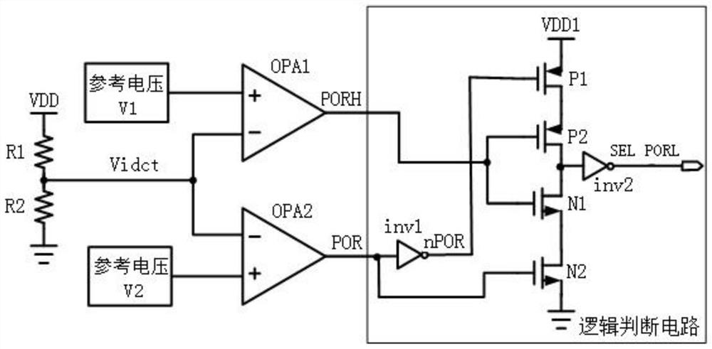
[0017] see figure 1 , the circuit of the specific embodiment of the present invention includes a comparison circuit and a logic judgment circuit, the comparison circuit includes a comparator OPA1 and a comparator OPA2, the negative input terminal of the comparator OPA1 is connected to the negative input terminal of the comparator OPA2, and the logic judgment circuit includes a voltage source VDD1 , pmos tube P1, pmos tube P2, nmos tube N1, nmos tube N2, inverter inv1 and inverter inv2, the voltage source VDD1 is connected to the source terminal of pmos tube P1, and the drain terminal of pmos tube P1 is connected to the source of pmos tube P2 The drain end of the pmos tube P2 is connected to the source end of the nmos tube N1, the gate of the pmos tube P2 is connected to the gate of the nmos tube N1, the drai...


PUM


Abstract

The invention relates to a dual-power-supply voltage real-time monitoring circuit and a monitoring method. The circuit comprises a comparison circuit and a logic judgment circuit, the comparison circuit comprises a comparator OPA1 and a comparator OPA2, the negative input end of the comparator OPA1 is connected with the negative input end of the comparator OPA2, the logic judgment circuit comprises a voltage source VDD1, a pmos tube P1, a pmos tube P2, a nmos tube N1, a nmos tube N2, a reverser inv1 and a reverser inv2. The voltage source VDD1 is connected with the source end of the pmos tube P1, the drain end of the pmos tube P1 is connected with the source end of the pmos tube P2, and the drain end of the pmos tube P2 is connected with the source end of the nmos tube N1. The grid electrode of the pmos tube P2 is connected with the grid electrode of the nmos tube N1, the drain end of the nmos tube N1 is connected with the source end of the nmos tube N2, the drain end of the nmos tube N2 is grounded, the output end of the comparator OPA1 is connected with the grid electrode of the pmos tube P2 and the grid electrode of the nmos tube N1, the output end of the comparator OPA2 is connected with the grid electrode of the pmos tube P1 and the grid electrode of the nmos tube N2, the inverter inv1 is connected between the output end of the comparator OPA2 and the grid electrode of the pmos tube P1, and the drain end of the pmos tube P2 and the source end of the nmos tube N1 are connected with the inverter inv2. The power supply state of the circuit can be detected in real time, accurate indication can be made, and it is guaranteed that a post-stage circuit is correspondingly started under the power supply voltage.

Description

technical field [0001] The invention relates to the field of integrated circuits, in particular to a dual power supply voltage real-time monitoring circuit and a monitoring method. Background technique [0002] With the continuous development of integrated circuits and the improvement of system complexity, chips powered by dual power supplies or even multiple power supplies are becoming more and more common. However, under different power supply voltages, large voltage differences will affect circuit performance, especially working performance under low power supply voltages. A commonly used power supply scheme is to use a power reference circuit and a low-dropout linear regulator to transfer different power supply voltages to a unified voltage for processing. [0003] Using a power reference circuit and a low-dropout linear regulator can transfer the power supply voltage to a lower voltage for processing, but for some analog circuits with many transistor layers, the power ...

Claims


Application Information

Patent Timeline
Patent Type & Authority Applications(China)
IPC IPC(8): H03K17/16G01R19/25
CPCG01R19/25H03K17/16
Inventor 吕俊盛田泽邵刚刘颖李嘉刘敏侠
Owner 西安翔腾微电子科技有限公司
Why Eureka
Try Eureka