Full-automatic assembling equipment for electric saw chains

An assembly equipment, fully automatic technology, applied in the direction of metal chains, etc., to achieve the effect of low cost, strengthen the fixing function, and prevent shaking and shifting

Pending Publication Date: 2021-04-09
WUHU JINGFENG GARDEN MACHINERY TECH
View PDF0 Cites 0 Cited by
  • Summary
  • Abstract
  • Description
  • Claims
  • Application Information

AI Technical Summary

Problems solved by technology

[0003] Aiming at the problem that large-scale automatic assembly equipment has a large volume and high input cost, the invention provides a fully automatic assembly equipment for electric saw chains. , fixed plate, clamping rod and other devices, effectively solve the problems raised in the background technology

Method used


Image

  • Full-automatic assembling equipment for electric saw chains
  • Full-automatic assembling equipment for electric saw chains
  • Full-automatic assembling equipment for electric saw chains

Examples


Embodiment 1

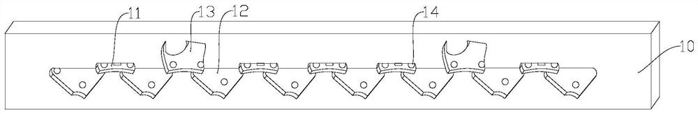
[0030] Such as Figure 1~6 As shown, it is a three-dimensional structural schematic diagram of a fixed plate in a fully automatic chainsaw chain assembly equipment. The automatic chainsaw chain assembly equipment of this embodiment includes a bottom chain plate 10, an upper chain plate 20, and a chain 40. One side of the lower chain plate 10 is provided with a connecting piece groove 11, a driving piece groove 12, and a blade groove 13. The inside of the lower loading chain plate 10 is provided with a first connecting hole 14, and the first connecting hole 14 runs through the Install the chain plate 10 below, the first connection hole 14 passes through the transmission piece groove 12, the blade groove 13, the described connection piece groove 11 is connected with two groups of transmission piece grooves 12 through the first connection hole 14, the described The drive slot 12 passes through the first connecting hole 14 and connects the blade slot 13. The drive slot 12 is distr...

Embodiment 2

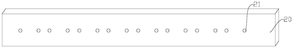
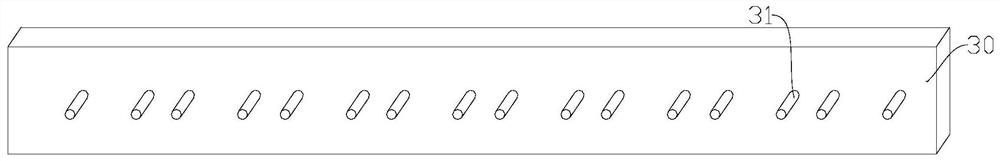
[0036] Such as image 3 As shown, it is a three-dimensional structural schematic diagram of a fully automatic assembly equipment for chainsaw chains in another preferred embodiment of the present invention. On the basis of Example 1, the construction safety protection improvement device of this example includes a fixing plate 30, so The fixed plate 30 is connected with the lower chain plate 10 through the clamping rod 31 and the first connecting hole 14, and the fixed plate 30 is connected with the upper chain plate 20 through the clamping rod 31 and the second connecting hole 21. There are sixteen groups of rods 31, and the clamping rods 31 are linearly arranged on one side of the fixing plate 30, and the positions of the clamping rods 31 correspond to the positions of the first connecting holes 14 one by one;


PUM


Abstract

The invention discloses full-automatic assembling equipment for electric saw chains, and belongs to the technical field of chain assembling. The full-automatic assembling equipment comprises a lower chain mounting plate, an upper chain mounting plate and a chain, wherein connecting sheet grooves, transmission sheet grooves and blade grooves are formed in one side of the lower chain mounting plate, first connecting holes are formed in the lower chain mounting plate, the first connecting holes penetrate through the lower chain mounting plate, the connecting sheet grooves are connected with the two groups of transmission sheet grooves through the first connecting holes, and the transmission sheet grooves are connected with the blade grooves through the first connecting holes. A chain assembly is mounted through the lower chain mounting plate, the connecting sheet grooves, the transmission sheet grooves, the blade grooves and the like, the overall device is low in manufacturing cost, the problems that large automatic assembling equipment is large in size and high in investment cost are solved, the fixing function on the chain assembly is enhanced through clamping rods connected to a fixing plate, and the chain assembly is prevented from shaking and deviating in the mounting process.

Description

technical field [0001] The invention belongs to the technical field of chain assembly, and in particular relates to a fully automatic assembly equipment for electric saw chains. Background technique [0002] Now, the chain is generally a metal link or ring, which is mostly used for mechanical transmission and traction. After the chain has been used for a period of time, or before leaving the factory, it must be lubricated with oil. One is for rust prevention, and the other is for assembly. When used in connection with gear parts, the purpose of lubricating transmission is achieved. In some small-scale manufacturers, when these components are assembled and docked to form a complete chain buckle, there is a lack of reasonable assembly mechanism. Large-scale automated assembly equipment The volume is large, the investment cost is high, and it is not suitable for small-scale applications. Those skilled in the art provide a subject to solve the problems raised in the above-mentio...

Claims


Application Information

Patent Timeline
Patent Type & Authority Applications(China)
IPC IPC(8): B21L9/06
CPCB21L9/065
Inventor 王泉福马国章张立群
Owner WUHU JINGFENG GARDEN MACHINERY TECH
Why Eureka
Try Eureka