
Cutting device for producing water sample detection sampling pipe

A technology for cutting devices and sampling tubes, which is applied in the direction of shearing devices, shearing devices, and attachments to shearing machines, etc., which can solve the problems of sampling tube movement, high cooling costs, and affecting the cutting accuracy of sampling tubes. Effects of life extension and thermal deformation prevention

Pending Publication Date: 2021-04-09
镇江和瑞环境技术有限公司
View PDF0 Cites 0 Cited by
  • Summary
  • Abstract
  • Description
  • Claims
  • Application Information

AI Technical Summary

Problems solved by technology

[0002] In the field of water sample detection, when extracting water samples at different depths, it is often necessary to insert the sampling tube to the specified depth, so it is necessary to make the sampling tube a length suitable for the water depth, so it is necessary during the production process. When using a cutting machine, the existing sampling tube is prone to movement during the cutting process, which affects the accuracy of the cutting incision of the sampling tube and brings certain troubles to the subsequent assembly of the sampling tube. In addition, the existing sampling tube When the cutting machine is cutting the sampling tube, there are few cooling structures to cool the cutting process, or the cooling cost is high. In this way, during the cutting process of the sampling tube, the cutter and the sampling tube are easily damaged by heat, and the debris cut out of the sampling tube is easy to Fly out and hurt

Method used


Image

  • Cutting device for producing water sample detection sampling pipe
  • Cutting device for producing water sample detection sampling pipe

Examples


Embodiment Construction

[0015] The present invention will be described in further detail below in conjunction with the accompanying drawings.

[0016] In describing the present invention, it should be understood that the terms "center", "longitudinal", "transverse", "upper", "lower", "front", "rear", "left", "right", " The orientations or positional relationships indicated by "vertical", "horizontal", "top", "bottom", "inner" and "outer" are based on the orientations or positional relationships shown in the drawings, and are only for the convenience of describing the present invention and Simplified descriptions, rather than indicating or implying that the device or element referred to must have a particular orientation, be constructed and operate in a particular orientation, and thus should not be construed as limiting the invention. In addition, the terms "first", "second", etc. are used for descriptive purposes only, and should not be understood as indicating or implying relative importance or imp...


PUM


Abstract

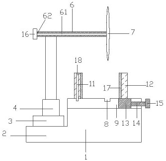
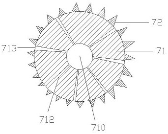
The invention discloses a cutting device for producing a water sample detection sampling pipe, and relates to the technical field of water sample detection, the cutting device comprises a workbench, a mounting base, a control box, an electric telescopic rod, a fixing plate and a cutter, a groove for accommodating the sampling pipe is formed in the surface of the workbench, and a sliding groove is formed in the workbench. A fixed clamping plate is arranged on the side, located in the groove, of the surface of the workbench, a movable clamping plate is arranged on the other side of the surface of the workbench, the lower end of the movable clamping plate is connected with a sliding rod through a sliding block, and the sliding rod is connected with a driving motor. The cutting device further comprises a cooling structure for cooling the cutter in the process of cutting the sampling pipe, the cooling structure is arranged in the cutting device for producing the water sample detection sampling pipe, the cutting cutter can be cooled, the service life of the cutter is prolonged, sparks are prevented from hurting people in the cutting process, and in addition, the sampling pipe can be prevented from being heated to deform.

Description

technical field [0001] The invention relates to the technical field of water sample detection, in particular to a cutting device for production of sampling tubes for water sample detection. Background technique [0002] In the field of water sample detection, when extracting water samples at different depths, it is often necessary to insert the sampling tube to the specified depth, so it is necessary to make the sampling tube a length suitable for the water depth, so it is necessary during the production process. When using a cutting machine, the existing sampling tube is prone to movement during the cutting process, which affects the accuracy of the cutting incision of the sampling tube and brings certain troubles to the subsequent assembly of the sampling tube. In addition, the existing sampling tube When the cutting machine is cutting the sampling tube, there are few cooling structures to cool the cutting process, or the cooling cost is high. In this way, during the cutti...

Claims


Application Information

Patent Timeline
Patent Type & Authority Applications(China)
IPC IPC(8): B23D21/00B23D33/02B23Q11/10
CPCB23D21/00B23D33/02B23Q11/10
Inventor 张付海顾海东王峰
Owner 镇江和瑞环境技术有限公司
Learn More