Cavity noise control method
A control method and cavity noise technology, which are used in aircraft control, affecting the air flow through the surface of the aircraft, aircraft parts, etc., can solve the problems of low applicability and the inability of the jet device to adjust the flow, and achieve a simple and easy configuration. The effect of machining and reducing cavity noise
- Summary
- Abstract
- Description
- Claims
- Application Information
AI Technical Summary
Problems solved by technology
Method used
Image
Examples
Embodiment 1
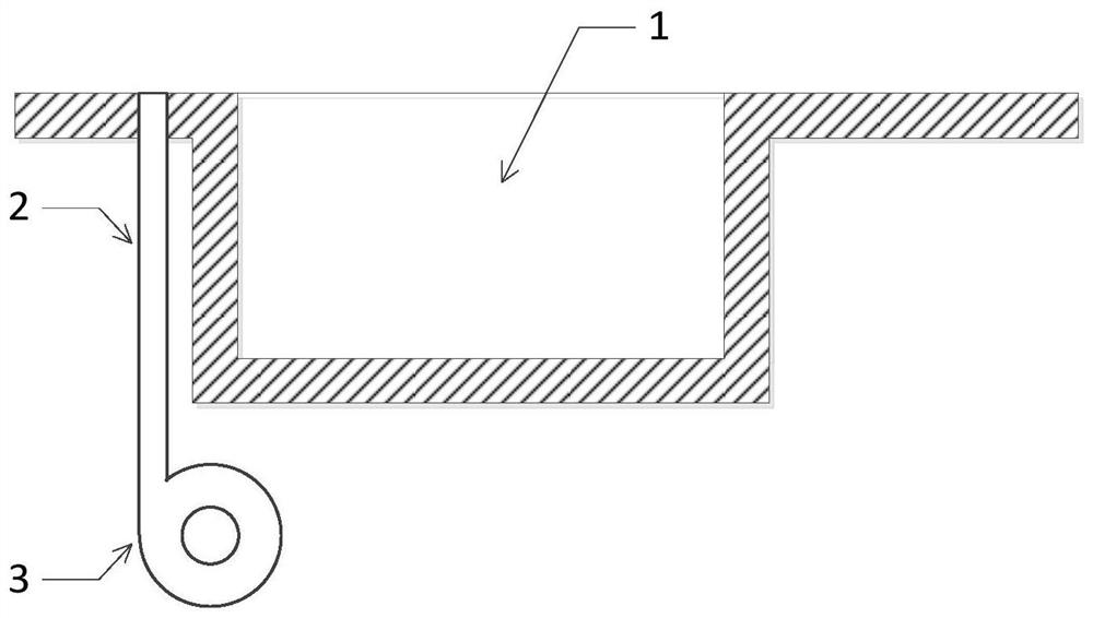
[0019] In this embodiment, combined with figure 1 As shown, there is provided a method of air blowing control at the leading edge of cavity 1 using an air blowing device for cavity noise control, which is used to reduce the internal noise of the cavity.
[0020] Wherein, the air blowing device includes an air blowing pipeline 2 and an air source device 3 . The outlet of the air blowing pipe 2 is located at an appropriate position in front of the front edge of the cavity 1, and the air source device 3 is arranged at a position below the front of the cavity. There is at least one outlet of the air blowing pipe 2, and there may be more than one. The outlet of the blowing duct 2 is arranged along the width direction of the cavity 1 . The gas source device 3 can use gases of different densities or temperatures.
[0021] Adjusting the flow rate of the blowing pipe 2 and the gas source device 3 can change the height of the shear layer at the leading edge of the cavity 1 and change ...
Embodiment 2
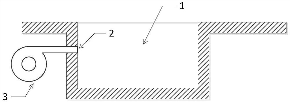
[0027] In this embodiment, combined with figure 2 As shown, another air blowing control method on the front wall of the cavity 1 is provided to reduce the internal noise of the cavity by using the air blowing device to control the cavity noise.
[0028] Wherein, the air blowing device includes an air blowing pipeline 2 and an air source device 3 . The outlet of the blowing duct 2 is located at an appropriate position on the front wall of the cavity 1, and the air source device 3 is arranged at a position below the front of the cavity. There is at least one outlet of the blowing duct 2, and there may be multiple outlets. The outlets of the blowing pipes 2 are symmetrically arranged along the width direction of the cavity 1 ; or arranged in accordance with the depth direction of the cavity 1 . The gas source device 3 can use gases of different densities or temperatures.
[0029] Adjusting the flow rate of the blowing pipe 2 and the air source device 3 can change the flow fed...
Embodiment 3
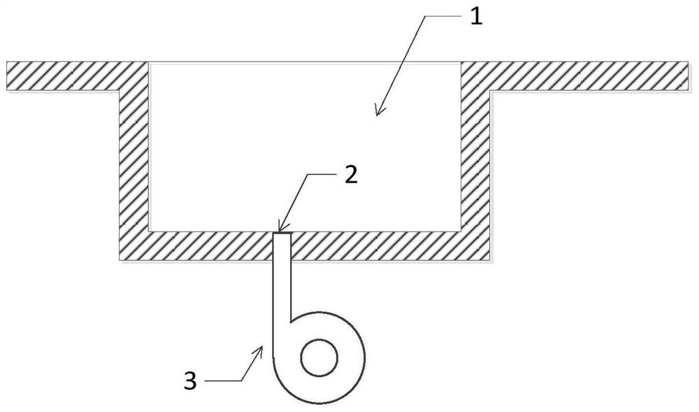
[0035] In this embodiment, combined with image 3 As shown, another air blowing control method at the bottom of the cavity 1 is provided to reduce the internal noise of the cavity by using the air blowing device to control the cavity noise.
[0036] Wherein, the air blowing device includes an air blowing pipeline 2 and an air source device 3 . The outlet of the blowing pipe 2 is located at a proper position on the bottom wall of the cavity 1, and the air source device 3 is arranged at a position below the cavity. There is at least one outlet of the blowing duct 2, and there may be multiple outlets. The outlets of the blowing pipes 2 are arranged symmetrically along the width direction of the cavity 1 ; or arranged along the length direction of the cavity 1 . The gas source device 3 can use gases of different densities or temperatures.
[0037] Adjusting the flow rate of the blowing pipe 2 and the air source device 3, on the one hand, reduces the vortex inside the cavity 1, ...
PUM
 Abstract
Description
Claims
Application Information
 - R&D
- Intellectual Property
- Life Sciences
- Materials
- Tech Scout
- Unparalleled Data Quality
- Higher Quality Content
- 60% Fewer Hallucinations
Browse by: Latest US Patents, China's latest patents, Technical Efficacy Thesaurus, Application Domain, Technology Topic, Popular Technical Reports.
© 2025 PatSnap. All rights reserved.Legal|Privacy policy|Modern Slavery Act Transparency Statement|Sitemap|About US| Contact US: help@patsnap.com


