
Discharging system for agricultural seeding unmanned aerial vehicle

A discharge system and UAV technology, applied in sowing seeders, sowing, agriculture, etc., can solve the problems of low UAV sowing area, low sowing efficiency, and reduced UAV flight mileage, so as to improve the sowing The effect of area area, improved accuracy, and improved seeding efficiency

Active Publication Date: 2021-04-09
宁夏绿先锋农业科技发展有限公司
View PDF7 Cites 0 Cited by
  • Summary
  • Abstract
  • Description
  • Claims
  • Application Information

AI Technical Summary

Problems solved by technology

This method not only consumes a large amount of electric energy of the UAV, but also reduces the flight mileage of the UAV, resulting in a lower area of ​​the UAV sowing area and lower overall sowing efficiency.

Method used


Image

  • Discharging system for agricultural seeding unmanned aerial vehicle
  • Discharging system for agricultural seeding unmanned aerial vehicle
  • Discharging system for agricultural seeding unmanned aerial vehicle

Examples


Embodiment 1

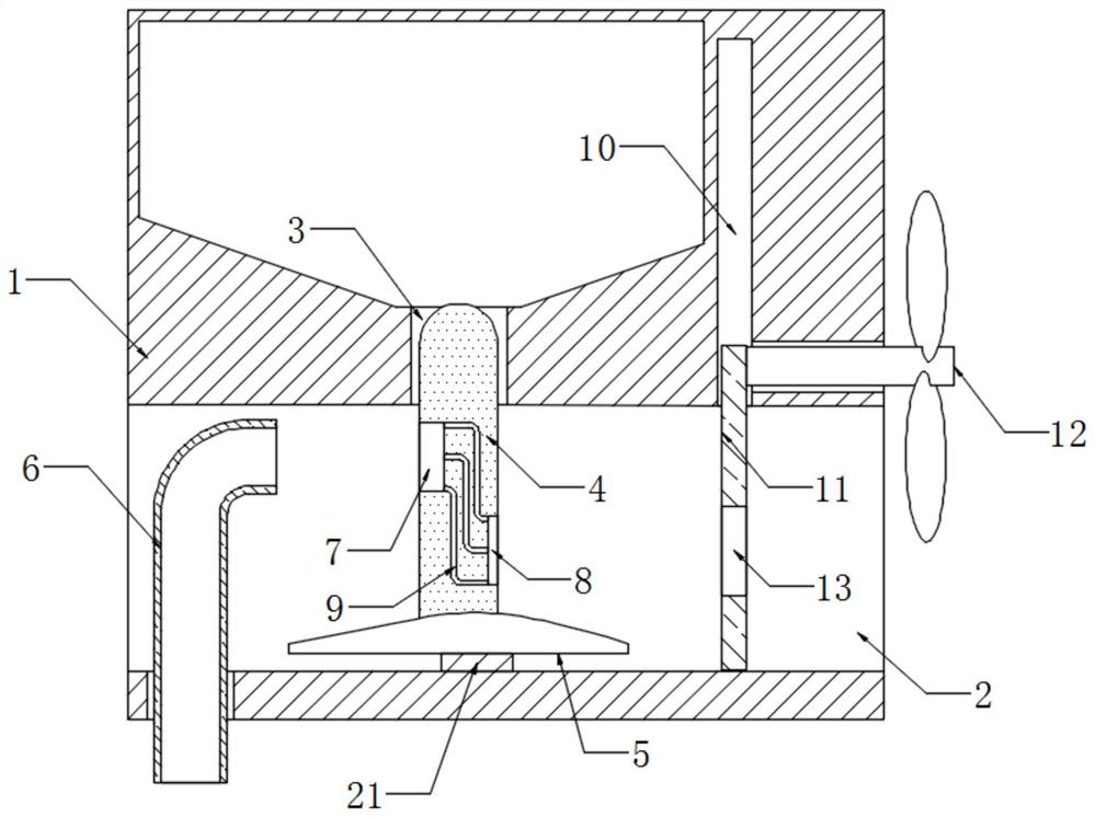
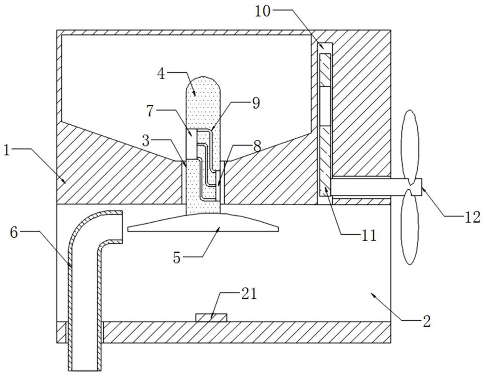
[0023] refer to Figure 1-2 , a discharge system for agricultural seeding unmanned aerial vehicles, including a storage bin 1, a vent 2 is provided on the side wall of the storage bin 1, and the vent 2 communicates with the inside of the storage bin 1 through a guide groove 3, and the guide A conveying plate 4 is slidably connected to the slot 3, and an airfoil 5 is fixedly connected to the lower end of the conveying plate 4. It should be noted that a spacer 21 is fixedly connected to the inner bottom of the vent 2 to support the airfoil 5. , to ensure that the airflow in the vent 2 can pass through the upper and lower sides of the airfoil plate 5, thereby generating a pressure difference between the upper and lower sides of the airfoil plate 5 and the ground airfoil plate 5 moving upward.

[0024] The vent 2 is embedded with an elbow 6, so that when the airflow is discharged along the elbow 6, it can finally be discharged vertically downwards, so that the seeds are given a ve...

Embodiment 2

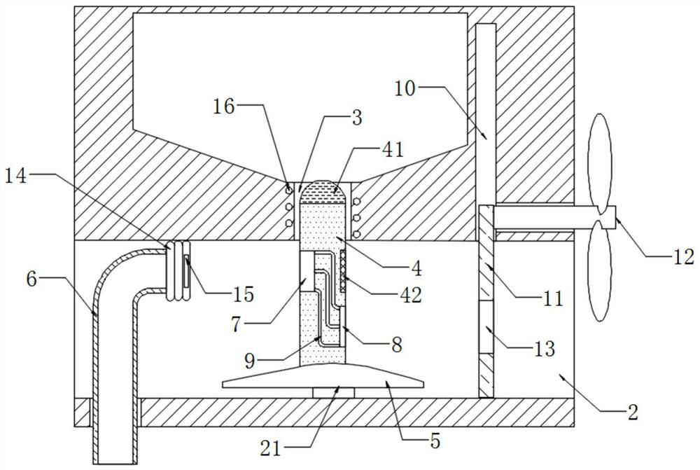
[0030] refer to image 3 , different from Embodiment 1, the inlet end of the elbow 6 is fixedly connected with a bellows 14 communicating with the inside, the bellows 14 is made of rubber material with good elasticity, and the side wall of the bellows 14 is fixedly connected with an electromagnet 15 , The side wall of the conveying plate 4 is fixedly connected with an iron sheet 42, the center of the iron sheet 42 is located on the same horizontal line as the center of the material storage port 7, and the bellows 14 is made of elastic rubber material. The power supply device to the electromagnet 15 is installed on the conveying plate 4, and the power supply device comprises a permanent magnet 41 fixedly connected on the conveying plate 4, and a closed helical coil 16 is embedded on the guide groove 3 inwall, and the helical coil 16 is connected with the electromagnet. Iron 15 is electrically connected.

[0031] It should be noted that since the permanent magnet 41 is only arr...


PUM


Abstract

The invention discloses a discharging system an agricultural seeding unmanned aerial vehicle. The discharging system comprises a storage bin, a ventilation opening is formed in the side wall of the storage bin, the ventilation opening communicates with the interior of the storage bin through a guide groove, a conveying plate is slidably connected into the guide groove, and a wing-shaped plate is fixedly connected to the lower end of the conveying plate; a bent pipe is embedded in the ventilation opening, a storage opening and an air inducing opening are formed in the two opposite side walls of the conveying plate respectively, the storage opening is communicated with the air inducing opening through a plurality of air pipes, and a lifting device enabling the wing-shaped plate to ascend and descend is installed on the storage bin. Seeds in the storage bin are continuously guided into the storage opening, the seeds in the storage opening are blown into the bent pipe through airflow to be discharged and conveyed, and compared with a discharging mode of a traditional seeding unmanned aerial vehicle, the device does not consume extra electric energy to prevent discharging blockage, the seeding area of the unmanned aerial vehicle is greatly increased, and the seeding efficiency is improved.

Description

technical field [0001] The invention relates to the related technical field of agricultural drones, in particular to a discharge system for agricultural sowing drones. Background technique [0002] In modern agricultural production, drones are already an indispensable operating equipment, among which seeding drones are a common type of agricultural drones. [0003] When the sowing drone is sowing seeds, in order to make the seeds go smoothly, mechanical agitation or pushing parts are often set in the storage box to continuously squeeze the seeds in the storage box. This method not only needs to consume a large amount of electric energy of the UAV, but also reduces the flight mileage of the UAV, resulting in a lower area of ​​the UAV sowing area and a lower overall sowing efficiency. Accordingly, this application document proposes a discharge system for agricultural seeding drones. Contents of the invention [0004] The purpose of the present invention is to solve the sho...

Claims


Application Information

Patent Timeline
Patent Type & Authority Applications(China)
IPC IPC(8): B64C39/02B64D1/02A01C7/08
CPCB64C39/02B64D1/02A01C7/082B64U2101/00
Inventor 赵月红
Owner 宁夏绿先锋农业科技发展有限公司
Learn More