Emergency risk avoiding device for highway bridge

It is a technology of a danger avoidance device and highway bridge, which is applied in the direction of bridges, bridge parts, bridge construction, etc., which can solve the problems of casualties, low practicability, and inability to achieve emergency avoidance, etc., to ensure safety, high applicability, and protection. wide range of effects

Pending Publication Date: 2021-04-09
陈文涛
View PDF6 Cites 2 Cited by
  • Summary
  • Abstract
  • Description
  • Claims
  • Application Information

AI Technical Summary

Problems solved by technology

[0002] With the continuous increase of highway mileage in our country, there are more mountainous areas in our country, and the roads are built along the mountains, so that one side of the highway is usually a deep valley, and at some turning points or roads with slopes, the prior art is open The patent No. CN202010432835.X provides an emergency avoidance device for highway bridges. The device has the following problems: 1. Only the guardrail of this device plays the role of emergency avoidance. When some vehicles with faster speeds pass through this road section accidents, causing the vehicle to crash the guardrail, and then fall to the bottom of the valley, causing casualties. It cannot prevent the vehicle from falling directly to the bottom of the valley, cannot guarantee the safety of vehicles and personnel, and cannot achieve reasonable emergency avoidance 2. In addition, the protective range of some anti-fall devices in the prior art is not large enough to automatically reach the working state of the device when an accident occurs; 3. In addition, some anti-fall devices in the prior art are inconvenient to install And it is not easy to transport, and the practicability is low. Therefore, it is particularly important to propose an emergency hedging device for a road with a valley on one side of the road. In view of this, we propose an emergency hedging device for highway bridges

Method used


Image

  • Emergency risk avoiding device for highway bridge
  • Emergency risk avoiding device for highway bridge
  • Emergency risk avoiding device for highway bridge

Examples


Embodiment Construction

[0027] In describing the present invention, it should be understood that the terms "center", "longitudinal", "transverse", "length", "width", "thickness", "upper", "lower", "front", " Orientation indicated by rear, left, right, vertical, horizontal, top, bottom, inside, outside, clockwise, counterclockwise, etc. The positional relationship is based on the orientation or positional relationship shown in the drawings, and is only for the convenience of describing the present invention and simplifying the description, rather than indicating or implying that the referred device or element must have a specific orientation, be constructed and operated in a specific orientation, Therefore, it should not be construed as limiting the invention.

[0028] In the description of the present invention, "plurality" means two or more, unless otherwise specifically defined.

[0029] In the description of the present invention, it should be noted that, unless otherwise specified and limited, t...


PUM


Abstract

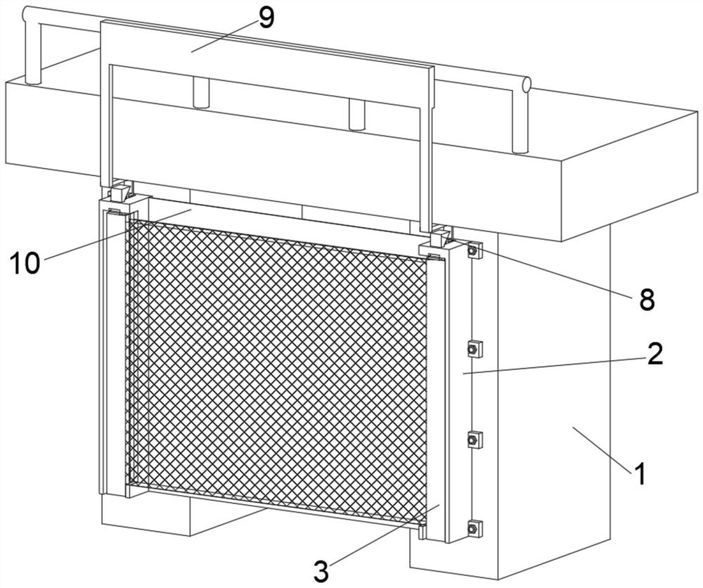
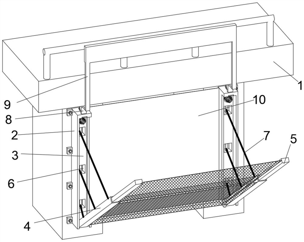
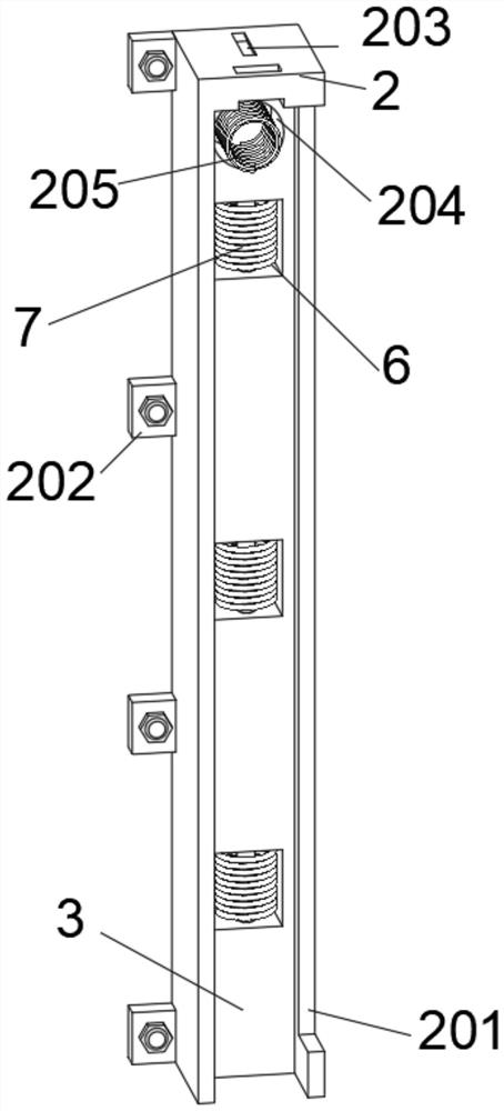
The invention discloses an emergency risk avoiding device for a highway bridge, and belongs to the technical field of highway bridge safety facilities. The emergency risk avoiding device for the highway bridge comprises a highway body, a baffle is arranged on the front side of the highway body, fixing plates are welded to the left end and the right end of the baffle, containing grooves are formed in the front sides of the fixing plates, rotating plates are arranged in the containing grooves, extending plates are sleeved with the upper ends of the rotating plates, and a plurality of containing grooves are formed in the inner walls of the rear sides of the containing grooves in a linear structure. A limiting assembly is arranged on the top face of the fixing plate in a penetrating mode, a transmission assembly is arranged on the front side of the upper end of the highway body, a steel wire mesh A is arranged on the rotating plate, and when a vehicle collides with a guardrail on the roadside, the rotating plate can form a certain included angle under the pulling force of the steel wire rope, so that a pocket is formed between the steel wire mesh A and the baffle, the falling vehicle can be held, and thus the vehicle is prevented from directly falling to the valley bottom, the safety of the vehicle and personnel is ensured, and the device plays a role of emergency risk avoiding.

Description

technical field [0001] The invention relates to the technical field of highway bridge safety facilities, and more specifically, relates to an emergency avoidance device for highway bridges. Background technique [0002] With the continuous increase of highway mileage in our country, there are more mountainous areas in our country, and the roads are built along the mountains, so that one side of the highway is usually a deep valley, and at some turning points or roads with slopes, the prior art is open The patent No. CN202010432835.X provides an emergency avoidance device for highway bridges. The device has the following problems: 1. Only the guardrail of this device plays the role of emergency avoidance. When some vehicles with faster speeds pass through this road section accidents, causing the vehicle to crash the guardrail, and then fall to the bottom of the valley, causing casualties. It cannot prevent the vehicle from falling directly to the bottom of the valley, cannot ...

Claims


Application Information

Patent Timeline
Patent Type & Authority Applications(China)
IPC IPC(8): E01D19/00E01D19/10
CPCE01D19/00E01D19/103
Inventor 陈文涛
Owner 陈文涛
Why Eureka
Try Eureka