Telescopic automatic pressure relief type anchor rod

An automatic unloading and bolting technology, applied in the installation of bolts, mining equipment, earth-moving drilling, etc., can solve the problems of single function, restricting the popularization and application of deformable bolts, and inability to relieve pressure multiple times.

Active Publication Date: 2021-04-09
SHANGHAI INST OF TECH
View PDF23 Cites 3 Cited by
  • Summary
  • Abstract
  • Description
  • Claims
  • Application Information

AI Technical Summary

Problems solved by technology

[0003]The currently developed deformable anchors can only withstand one deformation, cannot relieve pressure multiple times, and have a single function, which greatly limits the application of deformable anchors in rocks. Popularization and application in the field of soil engineering support

Method used


Image

  • Telescopic automatic pressure relief type anchor rod
  • Telescopic automatic pressure relief type anchor rod
  • Telescopic automatic pressure relief type anchor rod

Examples


Embodiment Construction

[0028] The telescopic automatic pressure-relieving anchor provided by the present invention will be described in further detail below in conjunction with the accompanying drawings and specific embodiments. Advantages and features of the present invention will be apparent from the following description and claims.

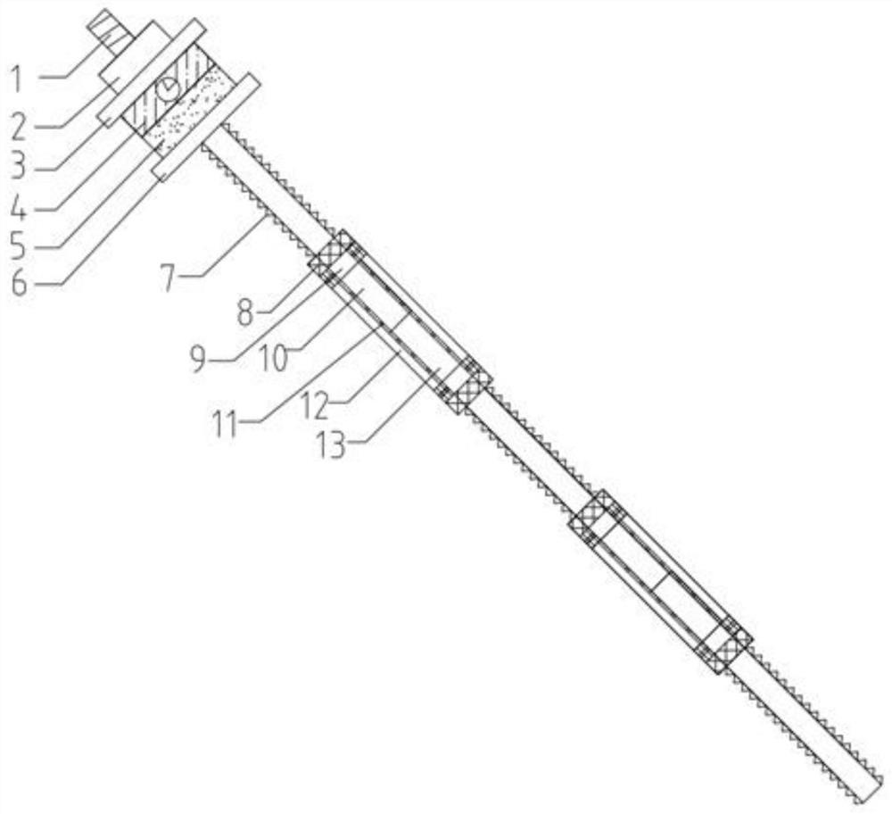
[0029] see figure 1 , a retractable automatic pressure relief bolt, including a bolt body 1, a pressure sensor 4, a connecting ring 12, a controller, a signal transmitter 5, and a signal receiver 8, and the top of the bolt body 1 is from top to bottom The fixing nut 2, the upper backing plate 3, the pressure sensor 4, the annular thin gasket, the signal transmitter 5 and the lower backing plate 6 are set in sequence, the top of the bolt body 1 is exposed outside the surrounding rock, and the fixing nut 2 and the upper backing plate 3 should be placed between rubber gaskets and thin iron sheets to prevent the nuts from being invalid due to uneven stress or temperatu...


PUM


Abstract

The invention discloses a telescopic automatic pressure relief type anchor rod. The telescopic automatic pressure relief type anchor rod comprises an anchor rod body, a pressure sensor, a connecting ring and a controller, wherein the anchor rod body at least comprises a first anchor rod body and a second anchor rod body; the connecting ring is arranged on the peripheral side of the joint of the first anchor rod body and the second anchor rod body, a telescopic fixing mechanism is arranged on the inner side of the connecting ring, the pressure sensor and the controller are arranged at the upper part of the anchor rod body, and the pressure sensor and the telescopic fixing mechanism are electrically connected with the controller; when the telescopic fixing mechanism is in a normal state, the telescopic fixing mechanism is fixedly connected with the anchor rod body; and when the telescopic fixing mechanism is in a contraction state, the anchor rod body is stretched under the action of pull. According to the telescopic automatic pressure relief type anchor rod, the pressure sensor and the telescopic fixing mechanism are arranged, so that the magnitude of the tensile force borne by the anchor rod can be measured, the anchor rod can be automatically stretched to relieve pressure when the borne tensile force is too large, and the deformation of surrounding rock is controlled for multiple times.

Description

technical field [0001] The invention belongs to the field of building construction, and in particular relates to a retractable automatic pressure-relieving anchor rod. Background technique [0002] With the further mining of coal in our country, the coal resources in open-pit coal mines and shallow strata are becoming less and less, and coal mining continues to develop to the deep. At the same time, the geological conditions of the roadway are becoming more and more complicated, and the deformation of the roadway surrounding rock is also increasing . Under the action of high ground stress, the existing bolts are often broken because they cannot bear the large deformation of the surrounding rock, so secondary support is often required, which not only wastes a lot of manpower and material resources, but also increases the difficulty of repair and prolongs the construction period. . Therefore, the bolts designed today should have a certain degree of flexibility, can automatic...

Claims


Application Information

Patent Timeline
Patent Type & Authority Applications(China)
IPC IPC(8): E21D21/02E21D21/00
CPCE21D21/02E21D21/0026E21D21/0033E21D21/0046
Inventor 仇圣华姜风周成张帅王晓彤徐宇豪
Owner SHANGHAI INST OF TECH
Why Eureka
Try Eureka