
Sealing structure with throttle orifice plate instead of valve

A technology of throttling orifice plate and sealing structure, which is applied to parts of pumping device for elastic fluid, non-variable displacement pump, machine/engine, etc. Adjusting the amount of water is difficult to quantitatively control, increasing the cost of mold opening and material management, etc., to avoid the operation of adjusting the amount of flushing water, facilitate material management, and facilitate installation.

Pending Publication Date: 2021-04-09
SHANGHAI KAIQUAN PUMP IND GROUP
View PDF0 Cites 0 Cited by
  • Summary
  • Abstract
  • Description
  • Claims
  • Application Information

AI Technical Summary

Problems solved by technology

[0002] The flushing pipeline of the existing single-stage double-suction horizontal split centrifugal pump has a structure with ball valves. The position of the ball valves is distributed on both sides of the top of the pump cover. Flushing performance; In addition, the generality of the mechanical seal and packing pump cover was not considered at the initial design stage, which increased the cost of mold opening and material management, and reduced the product's versatility

Method used


Image

  • Sealing structure with throttle orifice plate instead of valve
  • Sealing structure with throttle orifice plate instead of valve
  • Sealing structure with throttle orifice plate instead of valve

Examples


Embodiment Construction

[0019] The preferred embodiments of the present invention are given below in conjunction with the accompanying drawings to describe the technical solution of the present invention in detail.

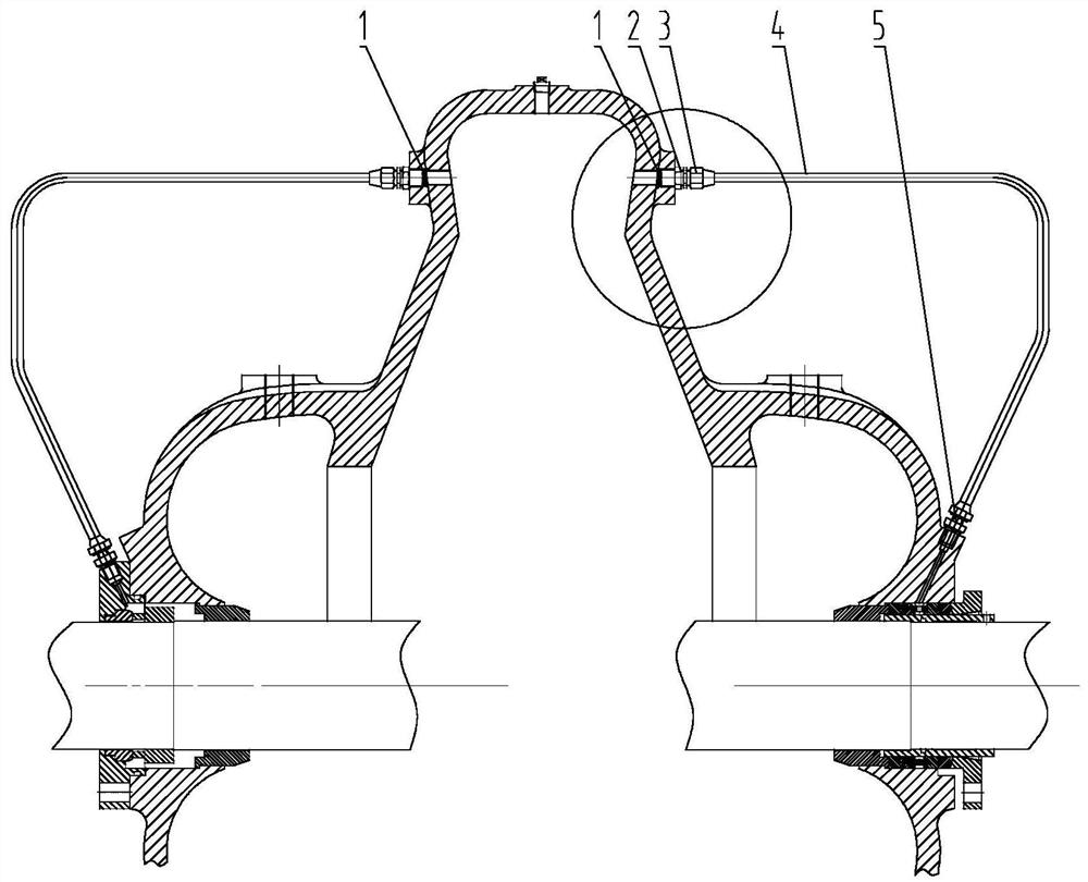
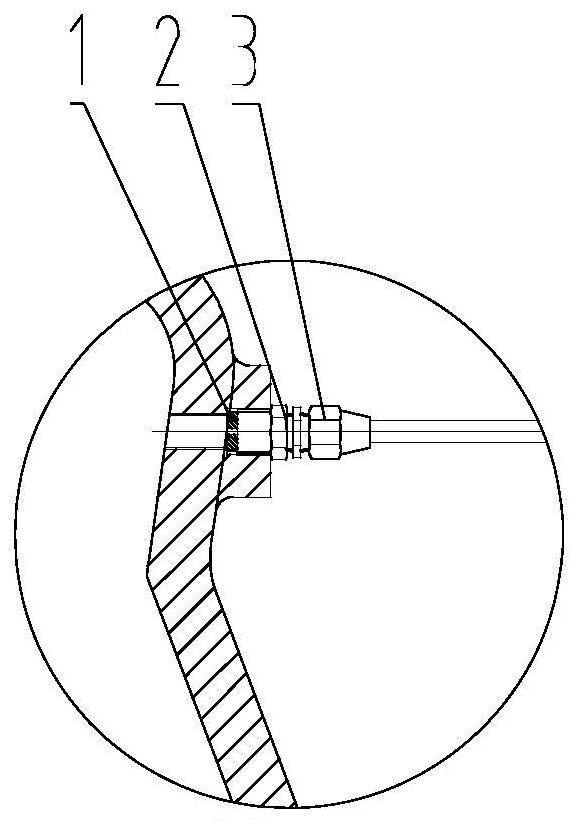
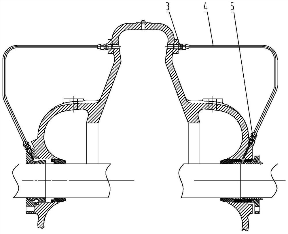
[0020] Picture 1-1 It is a schematic diagram of the sealing and flushing structure of the band throttle orifice of the present invention, Figure 1-2 for Picture 1-1 A partial enlargement of the . figure 2 It is a schematic diagram of the seal flushing structure without a throttle orifice plate of the present invention. As shown in the above figure: the throttling orifice provided by the present invention replaces the sealing structure of the valve, and the throttling orifice replaces the sealing structure of the valve and is installed in the double suction pump. The sealing structure of the throttling orifice replacing the valve includes: The flushing part, the seal flushing part includes the seal flushing pipeline and the seal flushing pipeline accessories matched with the seal flu...


PUM


Abstract

The invention relates to a sealing structure with a throttle orifice plate instead of a valve. The sealing structure with the throttle orifice plate replacing the valve is installed in a double suction pump, and comprises a sealing flushing part, wherein the sealing flushing part comprises a sealing flushing pipeline and a sealing flushing pipeline fitting matched with the sealing flushing pipeline, the sealing flushing pipeline is led out from two ends of a pump cover, and the two led-out ends are connected to a mechanical seal gland flushing hole or a reserved packing flushing hole of the pump cover. Compared with a traditional sealing flushing structure, the sealing structure with the throttle orifice plate instead of the valve provided by the invention overcomes the defects that: a flushing pipeline of a traditional single-stage double-suction horizontal split-case centrifugal pump is of a structure with ball valves, the positions of the ball valves are distributed at two sides of the top of the pump cover, the positions are high, the field operation difficulty is large, the water quantity is difficult to quantitatively adjust, the mechanical seal flushing performance is influenced, and in addition, the universality of a mechanical seal pump cover and a packing pump cover is not considered at the initial stage of design, the mold opening and material management cost is increased, and the product universality is reduced.

Description

technical field [0001] The invention relates to a sealing structure, in particular to a throttle orifice that is easy to install, reduces the difficulty of on-site operation, can avoid the operation of adjusting the amount of flushing water on site in the later stage, improves product versatility, and reduces cost in multiple directions. structure. Background technique [0002] The flushing pipeline of the existing single-stage double-suction horizontal split centrifugal pump has a structure with ball valves. The position of the ball valves is distributed on both sides of the top of the pump cover. Flushing performance; In addition, the versatility of the mechanical seal and packing pump cover was not considered at the early stage of design, which increased the cost of mold opening and material management, and reduced the versatility of the product. Contents of the invention [0003] In view of the above problems, the main purpose of the present invention is to provide a ...

Claims


Application Information

Patent Timeline
Patent Type & Authority Applications(China)
IPC IPC(8): F04D29/08F04D29/70F04D29/42
CPCF04D29/086F04D29/708F04D29/426
Inventor 王谦仇小宗杨志强常文强刘亚祜强盼侯凯文张耕春
Owner SHANGHAI KAIQUAN PUMP IND GROUP
Learn More