Shock absorber capable of self-adjusting lubrication according to vibration intensity
A vibration intensity and self-adjusting technology, which is applied in the direction of shock absorber, engine lubrication, spring/shock absorber design characteristics, etc., can solve problems such as inability to filter slight continuous vibration, manual adding lubricating oil error, affecting vibration damping performance, etc. , to achieve the effect of enhancing experience, improving ride comfort and reducing vibration amplitude
- Summary
- Abstract
- Description
- Claims
- Application Information
AI Technical Summary
Problems solved by technology
Method used
Image

Examples
Embodiment Construction
[0025] The following will clearly and completely describe the technical solutions in the embodiments of the present invention with reference to the accompanying drawings in the embodiments of the present invention. Obviously, the described embodiments are only some, not all, embodiments of the present invention. Based on the embodiments of the present invention, all other embodiments obtained by persons of ordinary skill in the art without making creative efforts belong to the protection scope of the present invention.
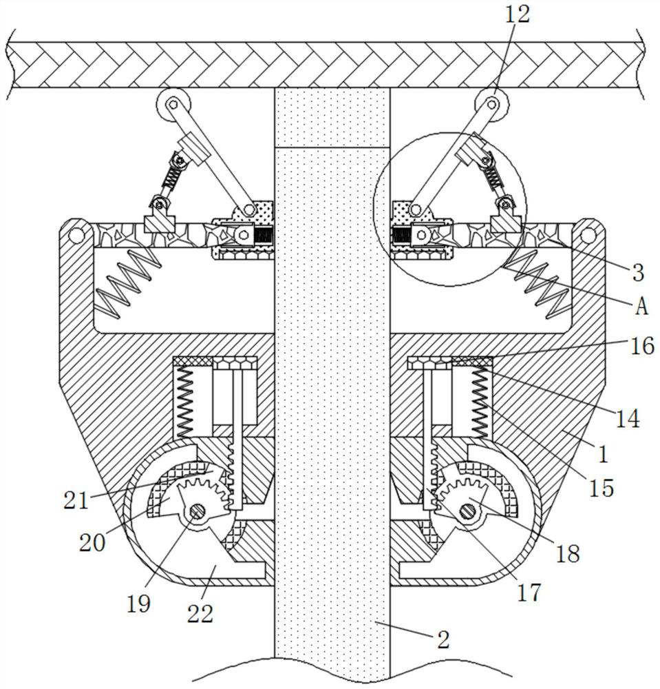
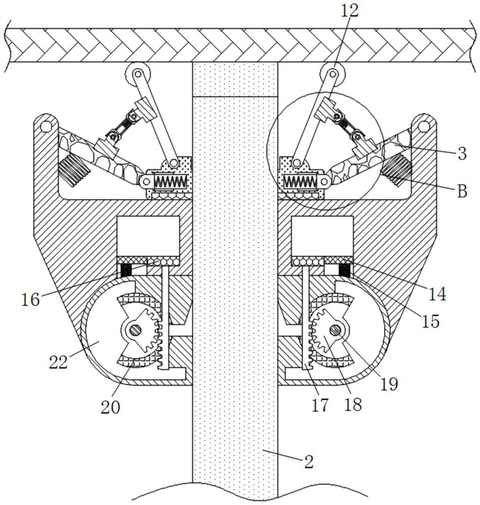
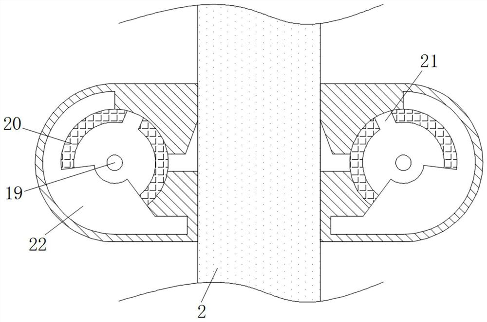
[0026] see Figure 1-6 , a shock absorber that self-regulates and lubricates according to the vibration intensity, including a frame body 1, a buffer frame 2 is movably connected to the center of the frame body 1, the interior of the frame body 1 is hollow, and the small surface of the top of the buffer frame 2 is abutted against the load roller 12 Above, the rotating rod 3 is arranged symmetrically about the center of the buffer frame 2. The lower surface of ...
PUM
 Abstract
Description
Claims
Application Information
PatSnap Eureka turns technology decisions into work you can execute. Powered by our Innovation Knowledge Graph, it runs expert workflows across engineering, life sciences, materials and intellectual property. Get your review-ready output in minutes.


