Energy-saving motor with rotating speed buffer function

A function and speed technology, applied in the field of energy-saving motors, can solve the problems that the acceleration effect cannot effectively supply the use requirements of energy-saving motors, cannot effectively buffer the speed, and the wear rate of the acceleration mechanism is large, so as to improve the protection effect, improve the coordination, and improve the The effect of the slowing effect

Pending Publication Date: 2021-04-09
曾伟德
View PDF3 Cites 0 Cited by
  • Summary
  • Abstract
  • Description
  • Claims
  • Application Information

AI Technical Summary

Problems solved by technology

[0003] The energy-saving motor in the prior art needs to be used with a deceleration mechanism during use to ensure the stable performance of the energy-saving motor running and stopping, and to improve the use effect, but the deceleration mechanism in the prior art is increasingly unable to meet social needs, and the acceleration effect cannot Effectively supply the use requirements of existing energy-saving motors, and the acceleration mechanism has a large wear rate during use, which will affect the deceleration effect after long-term use, cannot effectively play the effect of speed buffering, and affect the use effect. Therefore, the present invention proposes a An energy-saving motor with speed buffer function is used to solve the above problems

Method used


Image

  • Energy-saving motor with rotating speed buffer function
  • Energy-saving motor with rotating speed buffer function
  • Energy-saving motor with rotating speed buffer function

Examples


Embodiment Construction

[0020] The following will clearly and completely describe the technical solutions in the embodiments of the present invention with reference to the accompanying drawings in the embodiments of the present invention. Obviously, the described embodiments are only some, not all, embodiments of the present invention. Based on the embodiments of the present invention, all other embodiments obtained by persons of ordinary skill in the art without making creative efforts belong to the protection scope of the present invention.

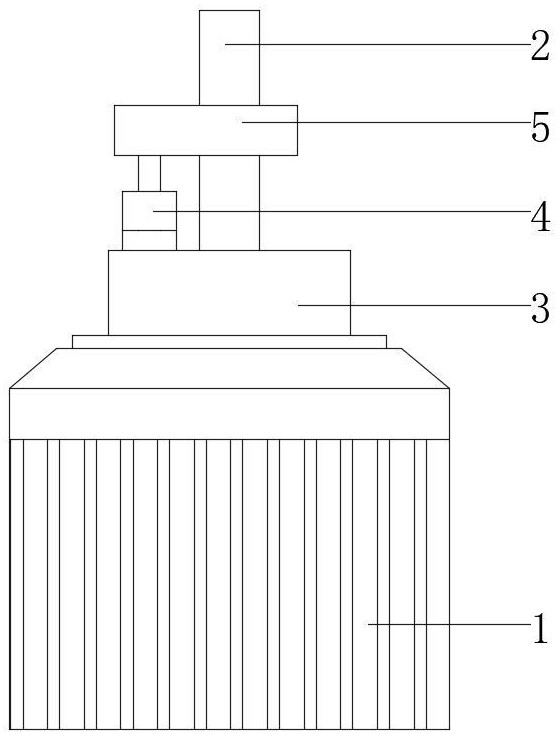
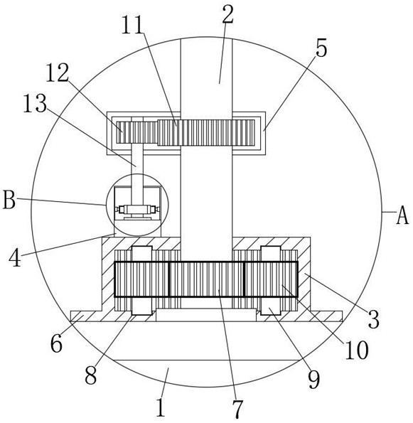
[0021] see Figure 1 to Figure 6 , the present invention provides a technical solution: an energy-saving motor with speed buffering function, including an energy-saving motor 1, a transmission shaft 2, a reduction box 3, a buffer box 4 and a transmission box 5, the energy-saving motor 1 is internally connected to the transmission shaft 2, The upper end of the transmission shaft 2 passes through the energy-saving motor 1 and is connected to the outside. The out...


PUM


Abstract

The invention relates to the technical field of motors, and particularly relates to an energy-saving motor with a rotating speed buffer function. The motor comprises an energy-saving motor, a transmission shaft, a reduction gearbox, a buffer box and a transmission box. The transmission shaft is in transmission connection with the interior of the energy-saving motor, and the upper end of the transmission shaft penetrates through the energy-saving motor and is connected to the outer side; the outer side of the transmission shaft at the upper end of the energy-saving motor is provided with the reduction gearbox; and a fixing base is arranged on the outer side of the reduction gearbox in a protruding mode, the fixing base is fixedly connected to the upper end of the energy-saving motor through a bolt, and the outer side of the upper end of the transmission shaft is provided with a fixed transmission box. The beneficial effects are that through cooperation of a speed reducing mechanism and a buffer mechanism, cooperation of the energy-saving motor and the rotation speed buffer mechanism can be effectively improved; and a speed reduction effect of the energy-saving motor in use is improved, the effect of rotating speed buffering can be effectively achieved, the protection effect on the speed reduction mechanism is improved, abrasion of the speed reduction mechanism is reduced, the service life of an acceleration mechanism is prolonged, the effect of cooperating with speed reduction can be achieved, and a use effect is improved.

Description

technical field [0001] The invention relates to the technical field of motors, in particular to an energy-saving motor with speed buffering function. Background technique [0002] The high-efficiency energy-saving motor adopts new motor design, new technology and new materials, and improves the output efficiency by reducing the loss of electromagnetic energy, heat energy and mechanical energy. The energy saving effect of using high-efficiency motors is very significant compared with standard motors, and the efficiency can be increased by an average of 4% in typical cases. [0003] The energy-saving motor in the prior art needs to be used with a deceleration mechanism during use to ensure the stable performance of the energy-saving motor running and stopping, and to improve the use effect, but the deceleration mechanism in the prior art is increasingly unable to meet social needs, and the acceleration effect cannot Effectively supply the use requirements of existing energy-s...

Claims


Application Information

Patent Timeline
Patent Type & Authority Applications(China)
IPC IPC(8): H02K7/116F16H1/32F16H57/02F16H57/021F16H57/028F16H57/00
CPCH02K7/116F16H1/32F16H57/02F16H57/021F16H57/028F16H57/0006F16H2057/02034F16H2057/02013F16H2001/327
Inventor 曾伟德罗明强
Owner 曾伟德
Why Eureka
Try Eureka