Structure for ensuring output precision of split-type rotary transformer

A rotary transformer and sub-package technology, which is applied in the direction of transformer, output power conversion device, AC power input conversion to AC power output, etc., can solve the problems of low installation accuracy, low reliability, and reduced output accuracy of the resolver. Achieve the effect of strengthening anti-interference performance and ensuring dynamic accuracy

Pending Publication Date: 2021-04-09
重庆虎溪电机工业有限责任公司
View PDF0 Cites 1 Cited by
  • Summary
  • Abstract
  • Description
  • Claims
  • Application Information

AI Technical Summary

Problems solved by technology

The resolver installation structure can ensure the output accuracy of the sub-package resolver. The existing sub-package resolver has the de

Method used


Image

  • Structure for ensuring output precision of split-type rotary transformer

Examples


Embodiment 1

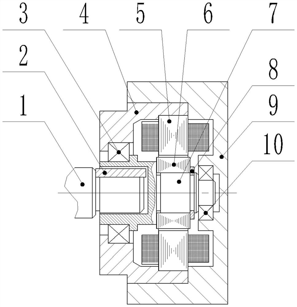
[0019] This embodiment discloses a structure for ensuring the output accuracy of a sub-package resolver, including a main shaft 1, a key 2, a bearing I3, a resolver mounting frame 4, a resolver stator 5, a resolver rotor 6, a resolver installation shaft 7, Back cover 9 and bearing II10.

[0020] The two sides of the resolver mounting frame 4 are marked as A side and B side respectively, and the cavity S inside the resolver mounting frame 4 runs through the A side and the B side. The main shaft 1 is arranged on the A side of the resolver mounting frame 4, and the back cover 9 is fastened on the B side of the resolver mounting frame 4 by using a seam, which can ensure the concentricity between the back cover 9 and the resolver mounting frame 4.

[0021] see figure 1 , the resolver stator 5, the resolver rotor 6 and the resolver mounting shaft 7 are all installed in the cavity S, the resolver mounting shaft 7 is connected to the inner wall of the resolver mounting frame 4 throug...

Embodiment 2

[0024] This embodiment discloses a structure for ensuring the output accuracy of a sub-package resolver, including a main shaft 1, a key 2, a bearing I3, a resolver mounting frame 4, a resolver stator 5, a resolver rotor 6, a resolver installation shaft 7, Back cover 9 and bearing II10.

[0025] The two sides of the resolver mounting frame 4 are marked as A side and B side respectively, and the cavity S inside the resolver mounting frame 4 runs through the A side and the B side. The main shaft 1 is arranged on the side A of the resolver mounting frame 4 , and the back cover 9 is fastened on the side B of the resolver mounting frame 4 .

[0026] see figure 1 , the resolver stator 5, the resolver rotor 6 and the resolver mounting shaft 7 are all installed in the cavity S, the resolver mounting shaft 7 is connected to the inner wall of the resolver mounting frame 4 through the bearing I3, and the resolver mounting shaft 7 Be connected on the inner wall of back cover 9 by bearin...

Embodiment 3

[0029] The main structure of this embodiment is the same as that of Embodiment 2, further, refer to figure 1 , the resolver rotor 6 is fixed on the resolver installation shaft 7 through a retaining ring 8 .


PUM


Abstract

The invention discloses a structure for ensuring the output precision of a split-type rotary transformer. The structure comprises a main shaft, a key, a rotary transformer installation frame, a rotary transformer stator, a rotary transformer rotor, a rotary transformer installation shaft and a rear cover. The rotary transformer stator, the rotary transformer rotor and the rotary transformer installation shaft are all installed in a cavity formed by the rotary transformer installation frame and the rear cover, the rotary transformer installation shaft is connected to the inner walls of the rotary transformer installation frame and the rear cover through bearings, the rotary transformer installation shaft is connected with the main shaft through the key, and a gap exists between the end face of the rotary transformer installation shaft and the end face of the main shaft. The rotary transformer rotor is fixed on the rotary transformer installation shaft, and the rotary transformer stator is arranged on the periphery of the rotary transformer rotor. The rotary transformer installation shaft is in floating connection with the main shaft, so that the influence of fluctuation generated by the main shaft on the rotary transformer rotor can be reduced, and the dynamic precision of the rotary transformer is ensured; and the rotary transformer installation device forms a closed shell, so that the anti-interference performance of the rotary transformer is remarkably enhanced.

Description

technical field [0001] The invention relates to the technical field of transformers, in particular to a structure for ensuring the output accuracy of a sub-package rotary transformer. Background technique [0002] In recent years, with the improvement of industrial automation level and the higher and higher requirements for energy saving and emission reduction, the application of high-efficiency and energy-saving permanent magnet AC motors has become more and more extensive. In the past, most of the position sensors on permanent magnet AC motors were optical encoders, but they were quickly replaced by resolvers in recent years. With a sub-package resolver, the resolver stator and rotor need to be assembled separately with the main engine, and the assembly error of the stator and rotor may cause the output accuracy of the resolver to deteriorate. The resolver installation structure can ensure the output accuracy of the sub-package resolver. The existing sub-package resolver ...

Claims


Application Information

Patent Timeline
IPC IPC(8): H02P13/00H02P6/18H01F38/18
CPCH02P13/00H02P6/18H01F38/18
Inventor 张典岳石浩赵浪杨彩李振东王茜刘睿
Owner 重庆虎溪电机工业有限责任公司
Why Eureka
Try Eureka