
Servo motor shaft locking method

A servo motor and shaft locking technology, applied in the field of intelligent robots, can solve problems such as high cost, servo motor oscillation and jitter, closed-loop system control errors, etc., and achieve the effect of high practicability, fast response speed, and powerful control.

Pending Publication Date: 2021-04-09
SHANGHAI YOGO ROBOTICS CO LTD
View PDF5 Cites 0 Cited by
  • Summary
  • Abstract
  • Description
  • Claims
  • Application Information

AI Technical Summary

Problems solved by technology

[0003] For a closed-loop system consisting of a current loop, a position loop and a speed loop, multiple sampling resistors are usually collected to sample the current of the servo motor. This not only increases the production cost of the acquisition structure, but also easily causes control errors in the closed-loop system. resulting in vibration and vibration of the servo motor
[0004] This article introduces a relatively simple and practical motor shaft locking method. In some applications that do not require high precision, if the standard control chip (DSP+FPGA) of advanced servo drives is used, the cost is too high, so it is not very suitable. , here is a more practical technique, which can be used in occasions where the positioning accuracy is not high but the rigidity of the lock shaft is large

Method used


Image

  • Servo motor shaft locking method
  • Servo motor shaft locking method
  • Servo motor shaft locking method

Examples


Embodiment Construction

[0042] In order to make the purpose, technical solution and advantages of the present application clearer, the implementation manners of the present application will be further described in detail below in conjunction with the accompanying drawings. Reference will now be made in detail to exemplary embodiments, examples of which are illustrated in the accompanying drawings. When the following description refers to the accompanying drawings, the same numerals in different drawings refer to the same or similar elements unless otherwise indicated. The described implementations described in the following exemplary embodiments do not represent all implementations consistent with this application. Rather, they are merely examples of apparatuses and methods consistent with aspects of the application as recited in the claims of the accompanying drawings.

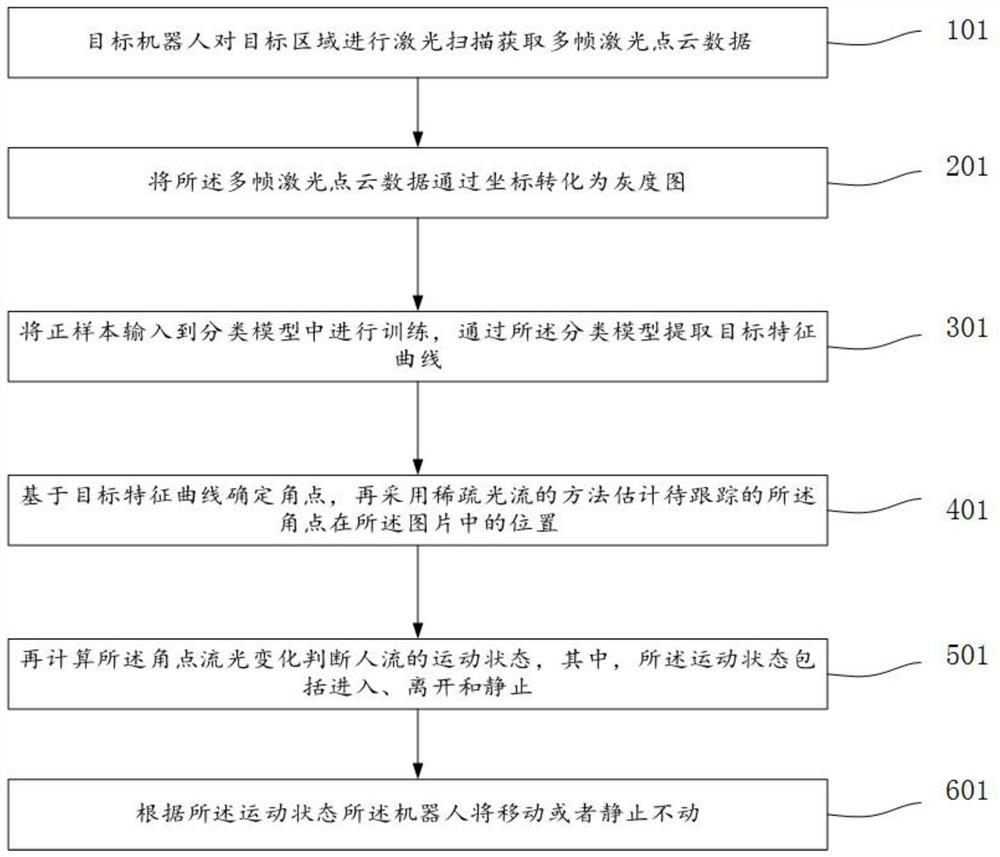
[0043] In some embodiments, the present invention provides a servo motor shaft locking method, in figure 1 shown in , including:...


PUM


Abstract

The invention provides a servo motor shaft locking method. The method comprises the following steps: acquiring rotation position information of a servo motor; presetting a first threshold value between a starting position and an ending position based on the rotation position information, wherein the position information does not fall into a first threshold range, and a first position loop, a first current loop and a first speed loop are adopted to control movement of the servo motor; and if the position information is within a first threshold range, adopting a second position loop and a second current loop to control the movement of the servo motor. The second position loop proportional integral adjustment mode comprises proportional and differential control; servo medium and low end control can be made as much as possible under the condition that hardware resources are weak, and the practicability is very high; the response speed of the modified position ring is higher, and the control is more powerful; and the method can be used in occasions with low requirements on positioning precision and higher rigidity of the lock shaft.

Description

technical field [0001] The invention relates to the field of intelligent robots, in particular to a shaft locking method for a servo motor. Background technique [0002] When controlling the servo motor, it can be controlled by at least one of the current loop, position loop and speed loop. Among them, the current loop can be understood as the control link with the current signal as the feedback signal, and the position loop can be understood as the As the control link of the feedback signal, the speed loop can be understood as the control link with the speed signal as the feedback signal. [0003] For a closed-loop system consisting of a current loop, a position loop and a speed loop, multiple sampling resistors are usually collected to sample the current of the servo motor. This not only increases the production cost of the acquisition structure, but also easily causes control errors in the closed-loop system. This will cause vibration and vibration of the servo motor. ...

Claims


Application Information

Patent Timeline
IPC IPC(8): H02P29/00H02P23/00H02P23/14H02P23/04
CPCH02P29/00H02P23/0004H02P23/14H02P23/04H02P2205/01H02P2205/07Y02P70/10
Inventor 颉友强
Owner SHANGHAI YOGO ROBOTICS CO LTD
Learn More