Eureka AIR delivers breakthrough ideas for toughest innovation challenges, trusted by R&D personnel around the world.

Refrigeration cycle device

A refrigeration cycle and refrigerant technology, applied in refrigerators, refrigeration components, power units, etc., can solve problems such as inability to adjust the temperature of secondary batteries

Pending Publication Date: 2021-04-09
DENSO CORP
View PDF2 Cites 0 Cited by
  • Summary
  • Abstract
  • Description
  • Claims
  • Application Information

AI Technical Summary

Problems solved by technology

[0012] In this regard, although the refrigeration cycle device described in Patent Document 1 can cool the secondary battery through the cooling unit, it cannot warm up the secondary battery.
Therefore, in the refrigeration cycle device disclosed in Patent Document 1, there is a possibility that the temperature of the secondary battery, which is the subject of temperature adjustment, cannot be appropriately adjusted.

Method used


Image

  • Refrigeration cycle device
  • Refrigeration cycle device
  • Refrigeration cycle device

Examples


Embodiment Construction

[0031] Hereinafter, a plurality of embodiments for implementing the present invention will be described with reference to the drawings. In each embodiment, parts corresponding to matters described in the previous embodiments may be denoted by the same reference numerals, and overlapping descriptions may be omitted. In each embodiment, when only a part of the structure is described, other embodiments described above can be applied to the other parts of the structure. In each embodiment, except for the combination of parts that can be specifically combined, the embodiments can be partially combined even if it is not explicitly stated, as long as the combination does not cause any particular trouble.

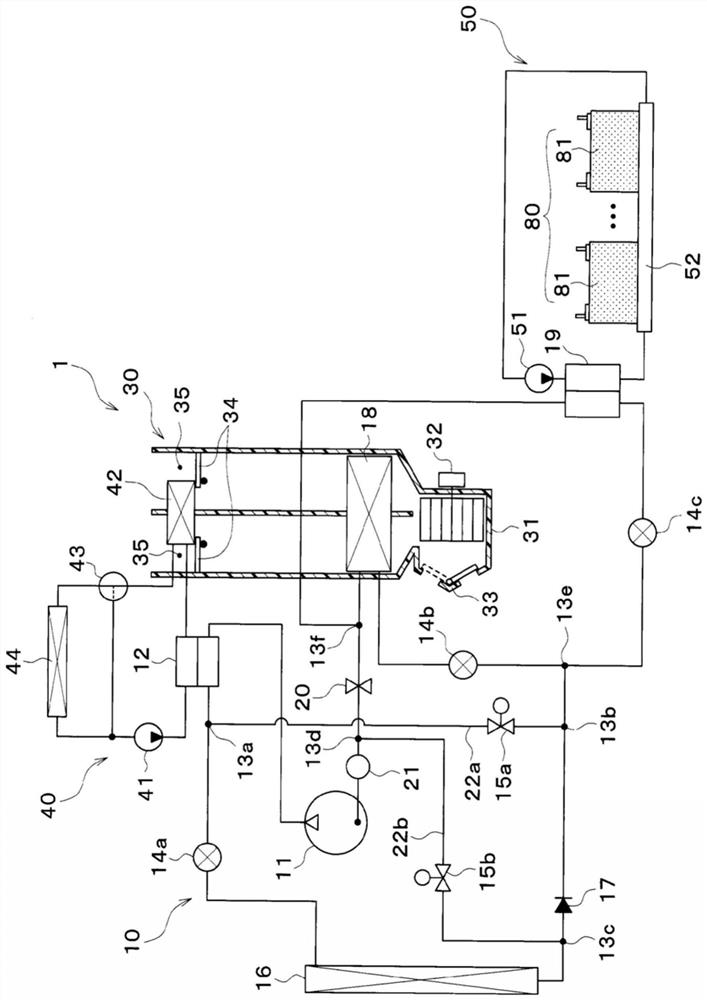
[0032] based on Figure 1 to Figure 6 , the embodiment in the present invention will be described. figure 1 It is a schematic configuration diagram of the vehicle air conditioner 1 of the present embodiment.

[0033] In the present embodiment, the refrigeration cycle device 10 o...


PUM


Abstract

This refrigeration cycle device (10) has a compressor (11), an outdoor heat exchanger (16), a decompression section (14b) for room cooling, an evaporator (18), a branch section (13e), a decompression section (14c) for cooling, a temperature regulation section (50), a confluence section (13f), a bypass passage (22a), and a first opening and closing valve (15a). The temperature regulation section (50) has a heat exchanger (19) for temperature regulation and regulates, using as the heat source a refrigerant flowing through the heat exchanger for temperature regulation, the temperature of an object (80), the temperature of which is to be regulated. In a room cooling / cooling mode for cooling blown air and the object, the temperature of which is to be regulated, the outdoor heat exchanger (16) is caused to function as a heat dissipater, and the evaporator (18) and the heat exchanger (19) for temperature regulation are caused to function as heat absorbers. In an object heating mode for heating the object, the temperature of which is to be regulated, a discharged refrigerant having been discharged from the compressor (11) is conducted through the bypass passage (22a) to the heat exchanger (19) for temperature regulation, and the object (80), the temperature of which is to be regulated, is heated using as the heat source the heat of the discharged refrigerant.

Description

[0001] Cross-reference of related applications [0002] This application is based on Japanese Patent Application No. 2018-166947 filed on September 6, 2018, the contents of which are cited here. technical field [0003] The invention relates to a refrigeration cycle device applied to an air conditioner. Background technique [0004] Conventionally, the technology described in Patent Document 1 is known as a refrigeration cycle device applied to an air conditioner. The refrigeration cycle device described in Patent Document 1 is applied to an air conditioner and is configured to be capable of cooling a secondary battery as a temperature adjustment object. [0005] The refrigeration cycle device of Patent Document 1 includes: a heating unit that uses high-pressure refrigerant discharged from a compressor as a heat source to heat blown air blown into a space to be air-conditioned; an indoor evaporator that cools the blown air by evaporating the low-pressure refrigerant; Cooli...

Claims


Application Information

Patent Timeline
IPC IPC(8): B60H1/22B60H1/32B60K11/02F25B1/00
CPCB60H1/32B60H1/22B60K11/02F25B2400/0409F25B2400/0411F25B41/22F25B25/005Y02E60/10F25B41/20F25B13/00
Inventor 多田和弘杉村贤吾小林宽幸加见佑一伊藤诚司
Owner DENSO CORP
Why Eureka
Eureka Blog
Learn More