
Warm-air heating machine

A technology for heating machines and heaters, which is applied in the direction of air heaters, fluid heaters, lighting and heating equipment, etc., and can solve the problems of insufficient heat, less heat, and difficult manufacturing and assembly of solid fuels.

Inactive Publication Date: 2008-08-13
魏善正
View PDF0 Cites 0 Cited by
  • Summary
  • Abstract
  • Description
  • Claims
  • Application Information

AI Technical Summary

Problems solved by technology

[0007] However, the focus of the above-mentioned conventional warm air heaters is mainly focused on enlarging the heat source of the stove and the heat exchange area of ​​conveying air, thus the structure is complicated, it is not easy to manufacture and assemble, and the manufacturing cost is increased.
[0008] That is, due to the complex structure of the heat exchange method, it is not only difficult to manufacture the heat exchanger, but also increases the manufacturing cost, and at the same time, the complicated heat exchange method significantly reduces the efficiency of the greenhouse
[0009] In addition, due to the use of gas or oil as energy, not only the cost of combustion is increased, the economy is reduced, but there are also serious noise problems in the furnace and the air supply device.
[0010] In addition to the above-mentioned structure, a variety of warm air heaters have been proposed that do not use gas or fuel oil, but instead use briquettes and lignite (hereinafter collectively referred to as "solid fuel") as energy sources. However, due to the insufficient heat of the solid fuel used, there are The problem of not being able to achieve the expected heating efficiency
[0011] The above-mentioned conventional warm air heaters supply solid fuel for combustion in one combustion space at one time, so the combustion efficiency is low, and the heat waste is serious. Compared with the combustion consumption, the heat released is less, and complete combustion cannot be achieved, resulting in Waste of energy. If the air is injected at high pressure to help it burn completely, slag will be formed due to the melting of the solid fuel burned in the combustion chamber, that is, briquettes or lignite, which will cause trouble for subsequent processing.

Method used


Image

  • Warm-air heating machine
  • Warm-air heating machine
  • Warm-air heating machine

Examples


Embodiment Construction

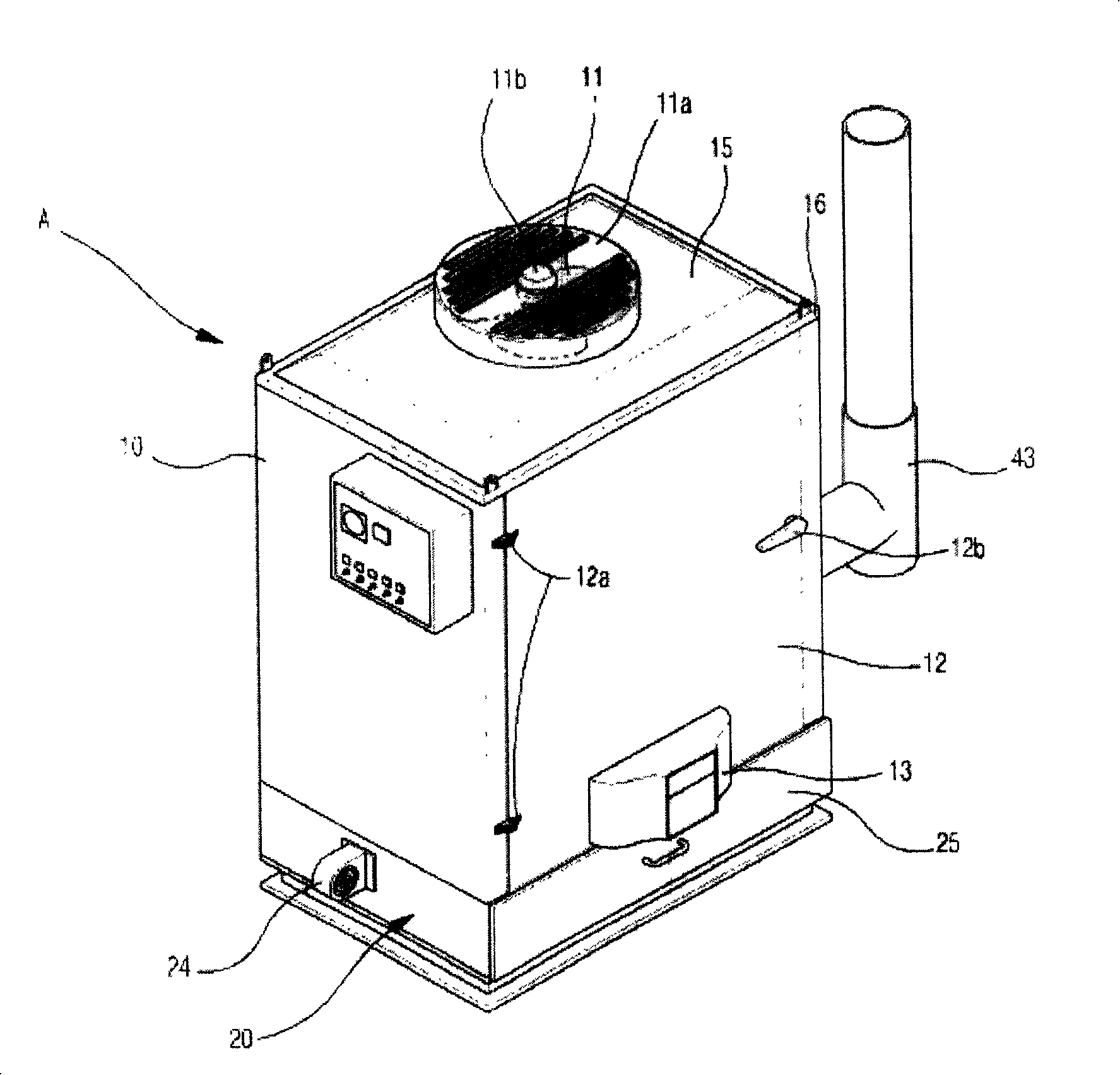
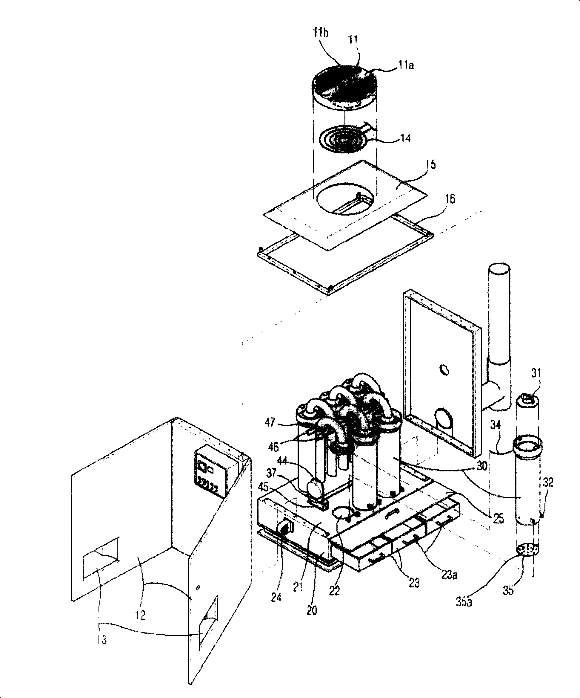
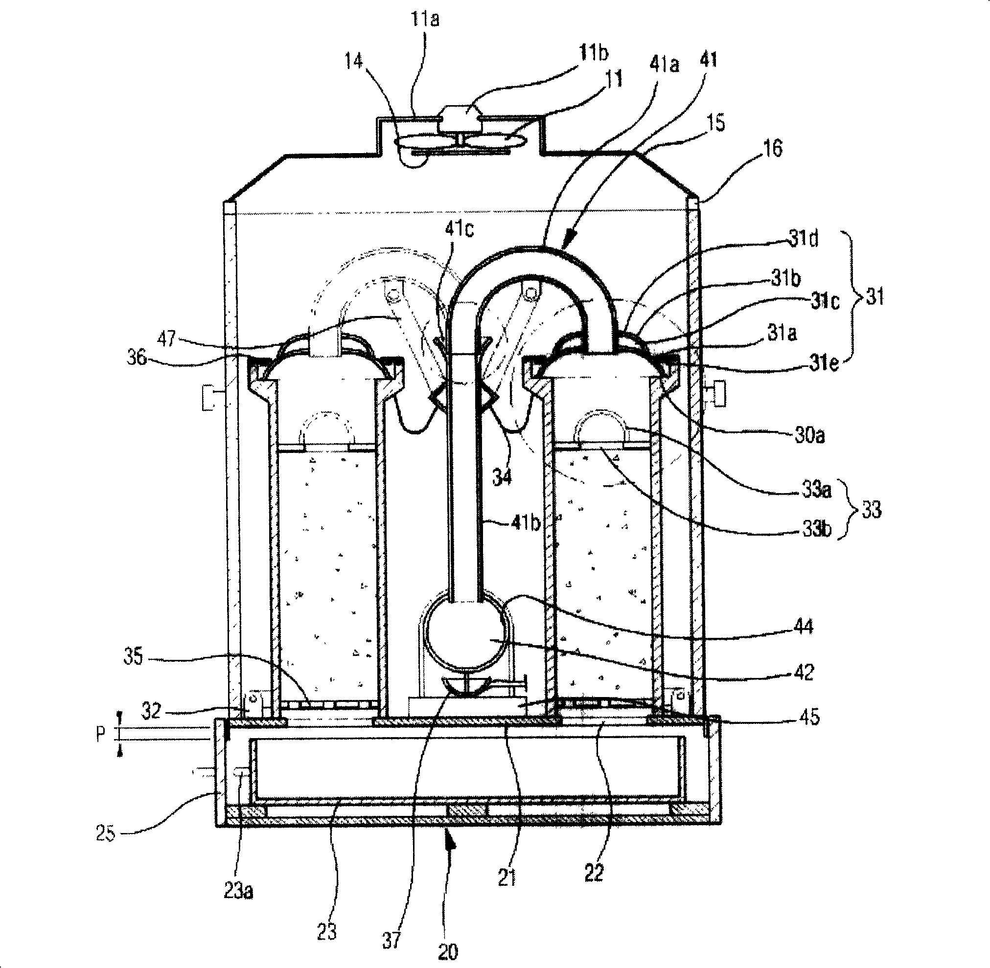
[0033] Referring to the accompanying drawings, the warm air heater of the present invention having the above characteristics will be described in detail.

[0034] In the warm air heater of the present invention, a fan 11 that blows air into the cylindrical body 10 is provided above the heater body A, that is, the cylindrical body 10, and a fan 11 that blows air into the cylindrical body 10 is provided on both sides of the cylindrical body 10 where the fan 11 is provided. The hinge 12a is a door 12 that can be opened and closed. A warm air outlet 13 for discharging warm air is formed on the door 12. A delivery pipe (not shown) is connected to the front end of the warm air outlet 13 . The above-mentioned fan 11 and the motor 11b are connected on the grid-shaped casing 11a.

[0035] In addition, a fan fixing plate 15 is also arranged above the body 10 provided with the fan 11 to provide safe and strong support for the fan 11, between the fan fixing plate 15 and the upper end of t...


PUM


Abstract

The present invention provides a warm braw heater, including a warm braw heater body, a solid fuel burning tank, a fume extractor and a blower, wherein, the warm braw heater body sets a fan on the top center of the cylinder body, the sides has gate forming warm braw outlet, the lower has ashpan having multiple pylomes on the top plate, the solid fuel burning tank is vertically set on the multiple pylomes on the ashpan plate, and the top is combined with the lid to ensure seal performance, and the lower has a rotary burning frame; the upper front of the vessel of the fume extractor is bent to ''í•'' shape, and the front of the vessel is connected to the burning case lid, the end of the vessel is connected to the outlet pipe fixed on the top plate; a drawer ashpan is set in the ashpan for receiving ashes generated in the burning case, a certain space is formed between the top surface of the ashpan and the top surface of the ashpan inner, and the blower is set on the side of the ashpan exterior.

Description

technical field [0001] The invention relates to a warm air heater for heating the inner space of a greenhouse (plastic greenhouse), and in particular relates to arranging a plurality of independent combustion boxes inside the body of the heater so that solid fuels are respectively burned in the plurality of combustion boxes, and the The hot air generated is supplied to the warm air heater in the inner space of the greenhouse (plastic greenhouse). Background technique [0002] Generally speaking, a greenhouse for cultivating various vegetables or various tropical plants requires a higher temperature for maintaining plant growth. In particular, when the external temperature drops sharply during the freezing period, it is necessary to supply relatively high-temperature air to the interior of the greenhouse through a heating device such as a boiler or a fan heater to maintain a certain temperature in the interior space. [0003] According to the type of fuel used or the way of ...

Claims


Application Information

Patent Timeline
IPC IPC(8): F24H3/04
Inventor 魏善正
Owner 魏善正
Learn More