
Spinning machine tool utilizing heat to generate deformation to increase suction to prevent deflection

A spinning machine tool and deformation technology, applied in metal processing equipment, etc., can solve the problems of cracks between the spinning wheel and the mandrel, increased hardness of the mandrel, deflection, etc., and achieve the effect of preventing the deflection of the mandrel and increasing the suction force

Inactive Publication Date: 2021-04-13
田明阳
View PDF0 Cites 0 Cited by
  • Summary
  • Abstract
  • Description
  • Claims
  • Application Information

AI Technical Summary

Problems solved by technology

[0003] In the prior art, when the spinning machine tool is in use, because there is a gap between the mandrel and the main shaft, and there is inevitably friction when the main shaft drives the mandrel, some particles will be generated, resulting in deflection, and the slow annealing speed leads to The hardness of the mandrel becomes larger, so that the contact between the rotary wheel and the mandrel produces cracks, so a

Method used

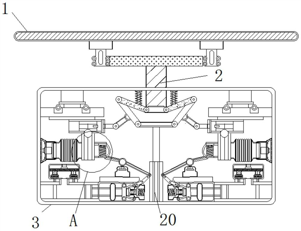

Image

  • Spinning machine tool utilizing heat to generate deformation to increase suction to prevent deflection
  • Spinning machine tool utilizing heat to generate deformation to increase suction to prevent deflection
  • Spinning machine tool utilizing heat to generate deformation to increase suction to prevent deflection

Examples


Embodiment Construction

[0020] The following will clearly and completely describe the technical solutions in the embodiments of the present invention with reference to the accompanying drawings in the embodiments of the present invention. Obviously, the described embodiments are only some, not all, embodiments of the present invention. Based on the embodiments of the present invention, all other embodiments obtained by persons of ordinary skill in the art without making creative efforts belong to the protection scope of the present invention.

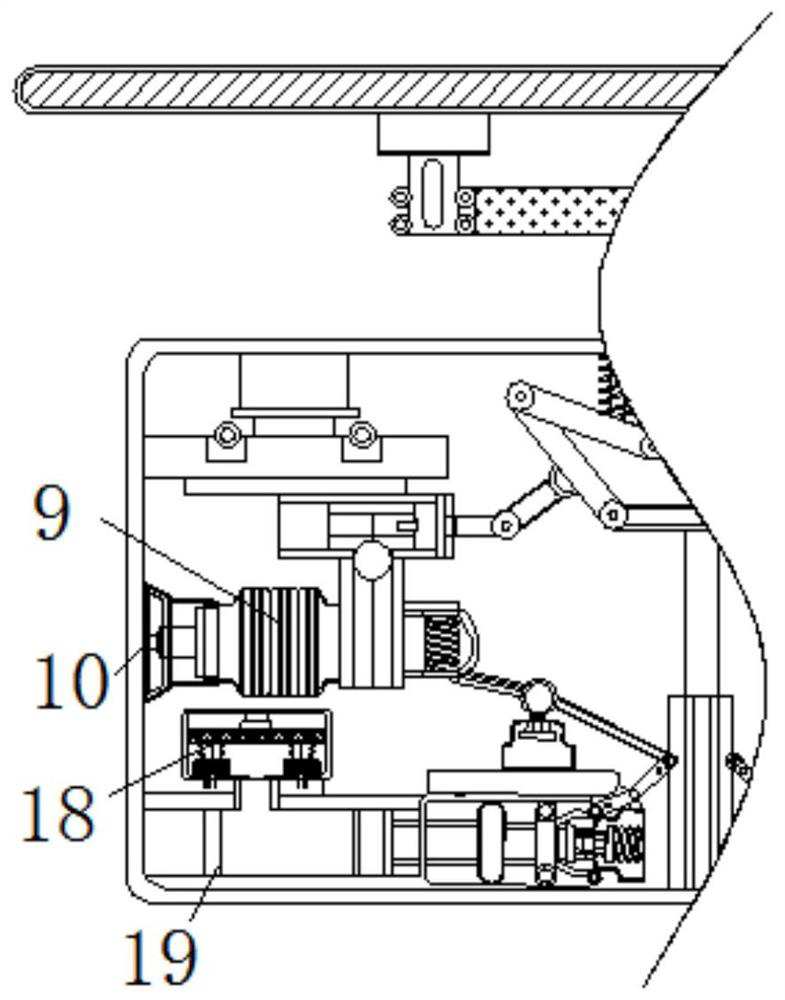
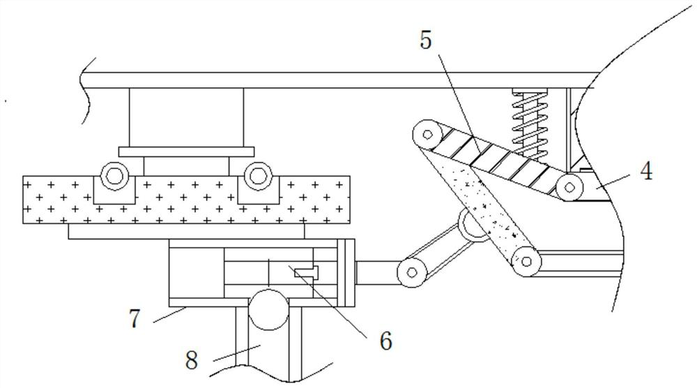
[0021] see Figure 1-5 , a spinning machine tool that uses heat to generate deformation and increase suction to prevent deflection, including a backing plate 1, the outer wall of the backing plate 1 is fixedly connected with a connecting rod 2, the outer wall of the backing plate 1 is movably connected with a spindle 3, and the outer wall of the backing plate 1 is movably connected with a spindle 3. The outer wall is movably connected with raw materials, the c...


PUM


Abstract

The invention relates to the technical field of machine tool manufacturing, and provides a spinning machine tool utilizing heat to generate deformation to increase suction to prevent deflection. The spinning machine tool comprises a base plate, a connecting rod is fixedly connected to the outer wall of the base plate, a spindle is movably connected to the outer wall of the connecting rod, and a connecting block is fixedly connected to the end, away from the base plate, of the connecting rod. According to the spinning machine tool utilizing heat to generate deformation to increase suction to prevent deflection, heated raw materials are arranged on the outer wall of the base plate in a sleeving mode, the base plate bears pressure to downwards drive the connecting rod to move, the connecting rod enables the connecting block to move, the connecting block and a first linkage rod are used in cooperation to enable a sliding block to move close to the main shaft, the sliding block drives a pressing plate to open an air bag, the expansion of the air bag requires inhalation, due to the fact that the outer wall of the main shaft is covered by the raw materials, the air bag sucks the raw materials inwards through a sucker, the air bag becomes larger due to the high temperature of the raw materials, the air bag sucks small particles between the main shaft and the raw materials, and the influence of the particles on spinning is prevented.

Description

technical field [0001] The invention relates to the technical field of machine tool manufacturing, in particular to a spinning machine tool that utilizes heat to generate deformation and increase suction to prevent deflection. Background technique [0002] The wheel hub is the part where the axle is installed in the center of the wheel. It is an important part of the car. With the development of the times, the wheel hub of the car has gradually begun to be produced by spinning. Spinning is to fix the hollow blank on the mold of the spinning machine. While the main shaft is rotating, press the blank with a rotary wheel or a driving rod to cause local plastic deformation. [0003] In the prior art, when the spinning machine tool is in use, because there is a gap between the mandrel and the main shaft, and there is inevitably friction when the main shaft drives the mandrel, some particles will be generated, resulting in deflection, and the slow annealing speed leads to The har...

Claims


Application Information

Patent Timeline
Patent Type & Authority Applications(China)
IPC IPC(8): B21D22/16B21D53/26
CPCB21D22/16B21D53/265
Inventor 田明阳
Owner 田明阳
Learn More