Multi-angle locating fixture for three-ball pin machining

A positioning fixture and multi-angle technology, applied in the direction of manufacturing tools, workpiece clamping devices, worktables, etc., can solve the problems of not having the ability to adjust and change angles, increasing operational difficulty, and low work efficiency, so as to improve user experience, The effect of simple and convenient operation and high work efficiency

Active Publication Date: 2021-04-13
浙江大升电子开发有限公司
View PDF7 Cites 0 Cited by
  • Summary
  • Abstract
  • Description
  • Claims
  • Application Information

AI Technical Summary

Problems solved by technology

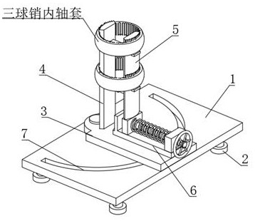
[0003] In the prior art, most tripod fixing fixtures can only fix one tripod inner bushing alone, and in the actual fixing operation process, the fixing operation is relatively cumbersome, and the fixing effect is poor, which in turn affects the work efficiency. , sometimes it is necessary to adjust the angle of the fixing device during processing. For example, when checking the processing situation, it is necessary to take out the three-ball pin for observation, or rotate the three-ball pin at different angles for observation, while most of the prior art The three-ball pin fixing fixtures do not have the ability to adjust and change the angle, their design is unreasonable, inconvenient to use, and the work efficiency is low, and most of the three-ball pin fixing fixtures in the prior art are all from the three-ball pin The outer surface is fixed, which occupies a large space, which brings certain adverse effects to subsequent processing operations and increases the difficulty of operation

Method used


Image

  • Multi-angle locating fixture for three-ball pin machining
  • Multi-angle locating fixture for three-ball pin machining
  • Multi-angle locating fixture for three-ball pin machining

Examples


Embodiment Construction

[0029] In order to make the technical means, creative features, goals and effects achieved by the present invention easy to understand, the present invention will be further described below in conjunction with specific embodiments.

[0030] In the description of the present invention, it should be noted that the terms "upper", "lower", "inner", "outer", "front end", "rear end", "both ends", "one end", "another end" The orientation or positional relationship indicated by etc. is based on the orientation or positional relationship shown in the drawings, and is only for the convenience of describing the present invention and simplifying the description, rather than indicating or implying that the referred device or element must have a specific orientation, use a specific Azimuth configuration and operation, therefore, should not be construed as limiting the invention. In addition, the terms "first" and "second" are used for descriptive purposes only, and should not be understood ...


PUM


Abstract

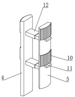
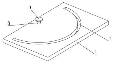
The invention discloses a multi-angle locating fixture for three-ball pin machining. The fixture comprises a bottom plate, wherein supporting feet are fixedly mounted at the four corners of the lower end of the bottom plate respectively, a mounting plate is fixedly mounted in the middle of the upper end of the bottom plate, a first clamping plate is fixedly mounted at the upper end of the mounting plate, an adjusting assembly is fixedly mounted on the rear portion of the upper end of the mounting plate, a second clamping plate is arranged at the upper end of the adjusting assembly, and a semi-annular groove is formed in the middle of the upper end of the bottom plate; the end faces, away from each other, of the first clamping plate and the second clamping plate are arc-shaped faces, the ends, away from each other, of the first clamping plate and the second clamping plate are fixedly connected with a plurality of protruding strips and supporting plates at equal intervals, and two stabilizing assemblies are jointly and fixedly connected between the first clamping plate and the second clamping plate. According to the multi-angle locating fixture for three-ball pin machining, the inner side of a three-ball pin inner shaft sleeve is fixed and supported, more space is reserved, subsequent machining operation can be facilitated, and the whole fixture is simple and rapid in fixing operation and good in fixing effect.

Description

technical field [0001] The invention relates to the field of auxiliary equipment for processing three-ball pins, in particular to a multi-angle positioning fixture for three-ball pin processing. Background technique [0002] The three-ball pin is mainly used for the inner ball cage of the four-wheel drive vehicle. It is suitable for the position of the inner ball cage with a small torsion angle. It has a compact structure. The needle determines the load-bearing torque of the universal joint. The maximum contact stress occurs at the contact point between the needle roller and the three-column shaft, which has a large axial slip and small slip resistance, strong transmission capacity, and fast heat dissipation. It has the advantages of simple processing technology, simple installation and reliable operation, etc. It can overcome the non-uniform velocity problem existing in ordinary cross shaft universal joints. The three-ball pin is fixed by a tooling fixture during the manuf...

Claims


Application Information

Patent Timeline
Patent Type & Authority Applications(China)
IPC IPC(8): B25B11/00B25H1/10
CPCB25B11/00B25H1/10Y02E10/50
Inventor 余银炜
Owner 浙江大升电子开发有限公司
Why Eureka
Try Eureka