Automatic mechanical arm belt wheel transmission mechanism

A technology of transmission mechanism and mechanical arm, applied in manipulators, program-controlled manipulators, manufacturing tools, etc., can solve the problems of easy heating of belts, easy heating of pulleys, and shortening of belt life.

Inactive Publication Date: 2021-04-13
杨明芹
View PDF8 Cites 0 Cited by
  • Summary
  • Abstract
  • Description
  • Claims
  • Application Information

AI Technical Summary

Problems solved by technology

[0007] In order to solve the above technical problems, the present invention provides an automatic mechanical arm pulley transmission mechanism to solve the existing problem that the belt of the existing device tends to heat up during the transmission process, and if the belt is in a high temperature state for a long time, the life of the belt is likely to be shortened , but cannot automatically realize the automatic cooling of the belt during the transmission process through structural improvements; moreover, the pulley tends to heat up under continuous working conditions, and it cannot be achieved through structural improvements while working. The problem of linkage with other structures to realize automatic cooling

Method used


Image

  • Automatic mechanical arm belt wheel transmission mechanism
  • Automatic mechanical arm belt wheel transmission mechanism
  • Automatic mechanical arm belt wheel transmission mechanism

Examples


Embodiment Construction

[0029] Embodiments of the present invention will be further described in detail below in conjunction with the accompanying drawings and examples. The following examples are used to illustrate the present invention, but should not be used to limit the scope of the present invention.

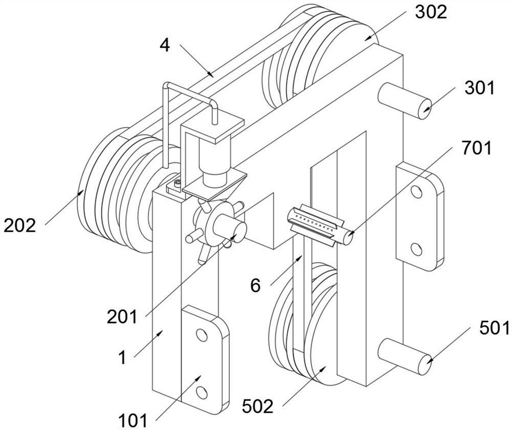
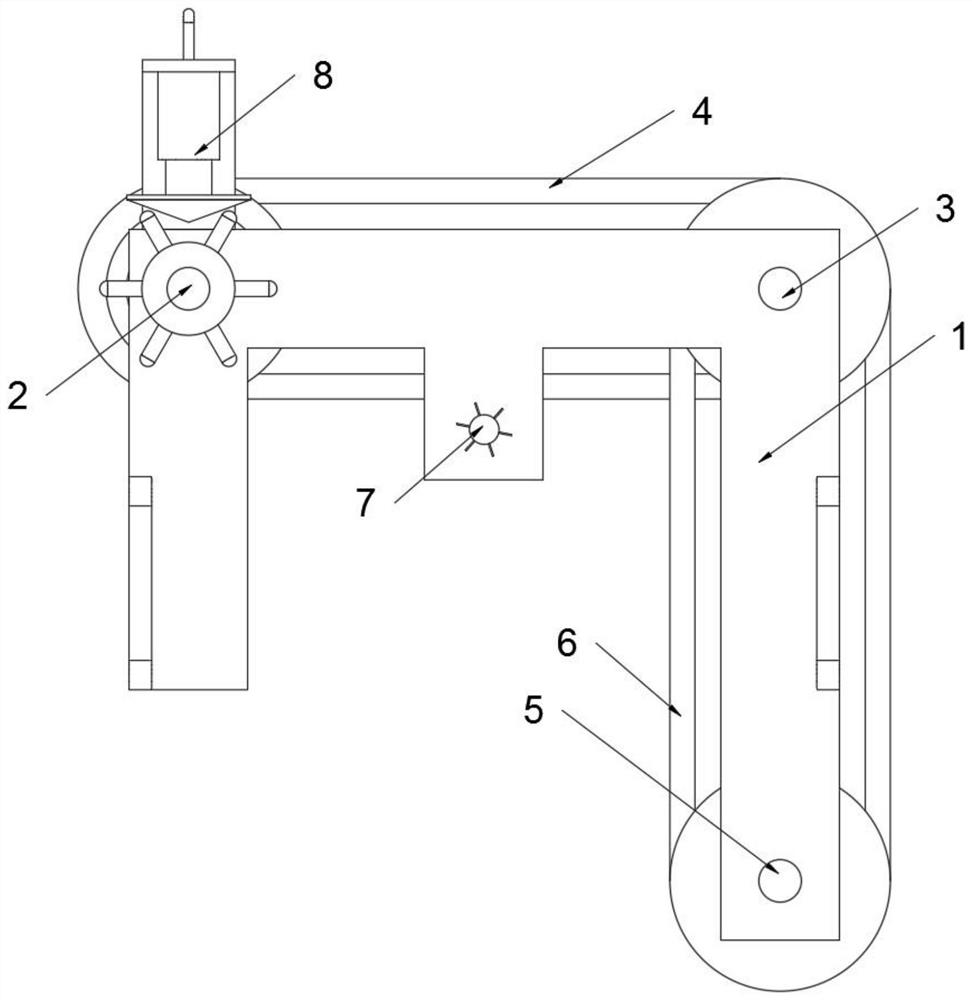
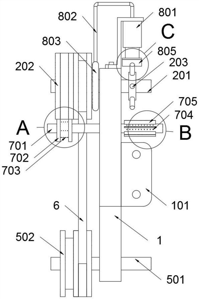
[0030] as attached figure 1 to attach Figure 7 Shown:

[0031] The present invention provides an automatic mechanical arm pulley transmission mechanism, which includes a base body 1; a first transmission structure 2, a second transmission structure 3, a third transmission structure 5 and an auxiliary structure 7 are rotatably connected to the base body 1, and the first transmission structure Structure 2 and the second transmission structure 3 are connected by belt A4, and the second transmission structure 3 and the third transmission structure 5 are connected by belt B6; refer to as image 3 and Figure 4 The auxiliary structure 7 includes a fourth rotating shaft 701, a tensioning wheel 702 a...


PUM


Abstract

The invention provides an automatic mechanical arm belt wheel transmission mechanism, and relates to the technical field of mechanical transmission structures. The problems that automatic air collection type cooling of a belt cannot be automatically realized in the transmission process through structural improvement, and other structures cannot be linked to realize automatic cooling during working through structural improvement are solved. The automatic mechanical arm belt wheel transmission mechanism comprises a base body; a first transmission structure, a second transmission structure, a third transmission structure and an auxiliary structure are rotationally connected to the base body; a through hole A is obliquely formed, and the inclination angle is -45 degrees, so that heat dissipation of a belt A can be realized when air is sprayed from the through the through hole A, and the through hole A formed at -45 degrees can reduce the resistance during rotation of a fourth rotating shaft and the friction force on the belt A; the inclination angle of through holes B is 45 degrees, and the through holes B formed in the annular array form an air collecting structure of the fourth rotating shaft, so that automatic air collection can be performed through the through holes B when the fourth rotating shaft rotates.

Description

technical field [0001] The invention belongs to the technical field of mechanical transmission structures, and more specifically relates to an automatic mechanical arm pulley transmission mechanism. Background technique [0002] With the continuous development of science and technology, the mechanical arm gradually replaces manual labor, and the mechanical arm often realizes the transmission work through multiple transmission structures when it is working. [0003] For example, the application number: CN201120366766.3, this utility model is an automatic mechanical arm pulley transmission mechanism, including a driving motor, a main pulley cooperating with the driving motor, and a first idler pulley and a second idler pulley located on both sides of the main pulley. The third idler pulley and the passive pulley, the third idler pulley and the passive pulley are flexibly wound together with the original main pulley, the first idler pulley and the second idler pulley through a ...

Claims


Application Information

Patent Timeline
Patent Type & Authority Applications(China)
IPC IPC(8): B25J9/10
CPCB25J9/104B25J9/1045
Inventor 杨明芹
Owner 杨明芹
Why Eureka
Try Eureka