Eureka AIR delivers breakthrough ideas for toughest innovation challenges, trusted by R&D personnel around the world.

Three-phase separator

A three-phase separator and main body technology, which is applied in the field of water treatment, can solve the problems of easy mud running, poor solid and liquid separation effect, etc., and achieve the effect of complete separation, reduced impact and good separation effect

Pending Publication Date: 2021-04-13
帕克环保技术(上海)有限公司
View PDF0 Cites 7 Cited by
  • Summary
  • Abstract
  • Description
  • Claims
  • Application Information

AI Technical Summary

Problems solved by technology

However, since the gas, solid and liquid three-phase separation of the three-phase separator is carried out at the same time, the gas is not separated in advance, and there will be gas disturbance during the solid-liquid separation process, resulting in poor solid-liquid separation effect and easy mud run-off

Method used


Image

  • Three-phase separator
  • Three-phase separator

Examples


Embodiment Construction

[0036]Embodiments of the present invention will be described in detail below, and examples of the embodiments are illustrated in the drawings, in which the same or similar reference numerals represent the same or similar elements or elements having the same or similar functions. The following is exemplary, and is intended to be used herein, not to be construed as limiting the invention.

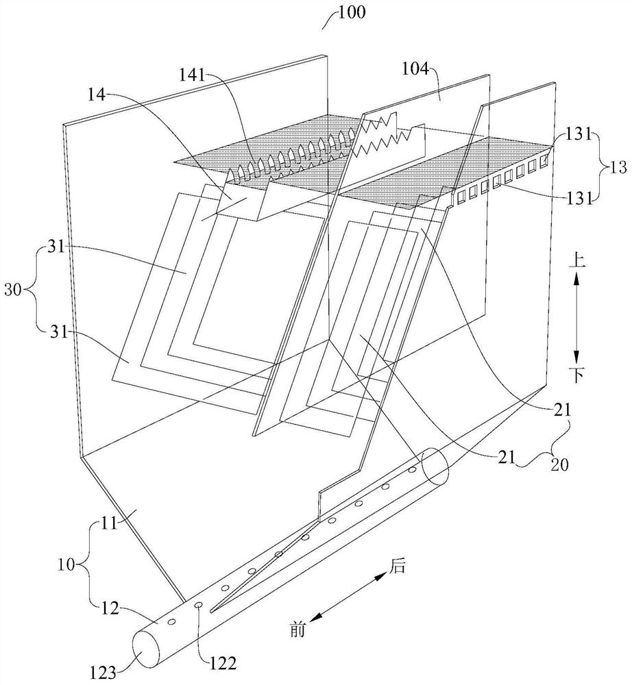
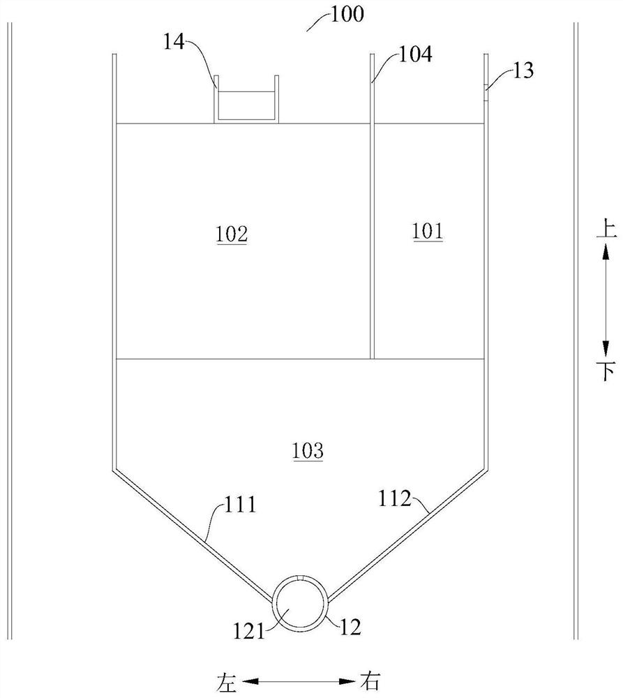
[0037]BelowFigure 1 - Figure 2A three-phase separator 100 in accordance with an embodiment of the present invention is described.

[0038]Such asfigure 1 withfigure 2 As shown, the three-phase separator 100 according to an embodiment of the present invention includes a main body 10, and the body 10 defines a degassing chamber 101, a precipitation chamber 102, and a storage chamber 103, and the storage chamber 103 is located below the degasser 101 and the precipitation chamber 102. The degasser 101, the sedimentation chamber 102 is arranged at the horizontal direction, and the storage chamber 103 communic...


PUM


Abstract

A disclosed three-phase separator comprises a main body, a degassing device and a precipitation device; the main body defines a degassing cavity, a precipitation cavity and a storage cavity which are arranged at intervals in the horizontal direction, the storage cavity is located below the degassing cavity and the precipitation cavity, the storage cavity communicates the degassing cavity with the precipitation cavity, and the main body is provided with a feeding part located on the upper portion of the degassing cavity and a liquid outlet part located on the upper portion of the precipitation cavity; the degassing device is arranged in the degassing cavity and is used for separating out gas in a mixture entering the degassing cavity; the precipitation device is arranged in the precipitation cavity and is used for separating liquid and solid in the mixture entering the precipitation cavity; and a closed structure is formed at the bottom of the storage cavity, and solids in the storage cavity are suitable for being pumped out through a suction device. According to the three-phase separator provided by the embodiment of the invention, the bottom of the storage cavity is arranged to be of the closed structure, so that liquid and gas at the bottom of the storage cavity are prevented from interfering with solids, the gas, the liquid and the solids are separated more thoroughly, and the separation effect is better.

Description

Technical field[0001]The present invention relates to the field of water treatment, in particular, to a three-phase separator.Background technique[0002]The three-phase separator can be applied to aerobic, anaerobic reactor, for separation of gas, water, sludge, based on separation cost and process control, the aerox reactor is generally used by three-phase separator for separation The three-phase separator is widely used in anaerobic reactor.[0003]The bottom of the three-phase separator in the related art is provided with a human flame flap, and the character flaking plate is limited to the opening, which is convenient to discharge the sludge. However, since the gas, solid and liquid three phase separation of the three-phase separator is carried out at the same time, the gas does not separate, in the solid and liquid separation process, the gas is disturbed, resulting in the difference in solid, liquid separation, easy to run.Inventive content[0004]The present invention is intended ...

Claims


Application Information

Patent Timeline
Patent Type & Authority Applications(China)
IPC IPC(8): C02F3/28
CPCC02F3/2866C02F2203/006C02F2303/14
Inventor 李静
Owner 帕克环保技术(上海)有限公司
Why Eureka
Eureka Blog
Learn More