
A water circulation device for sponge city landscape

A sponge city and water cycle technology, applied in watering devices, water supply devices, grease/oily substances/floating matter removal devices, etc., can solve problems such as adjusting watering frequency, increasing the use of manpower, and surface runoff

Active Publication Date: 2022-02-15
重庆泛奥园林景观设计有限公司
View PDF9 Cites 0 Cited by
  • Summary
  • Abstract
  • Description
  • Claims
  • Application Information

AI Technical Summary

Problems solved by technology

[0002] Sponge city is a new generation of urban stormwater management concept. It means that the city can be like a sponge, and has good elasticity in adapting to environmental changes and dealing with natural disasters caused by rainwater. It can also be called "water elastic city". The international general term is "low-impact development rainwater system construction". When it rains, water is absorbed, stored, infiltrated, purified, and the stored water is released and utilized when needed. It can be seen everywhere in parks and green spots in the city. Parks and Greening points can beautify the city and improve the air quality of the city, but the current green belts have poor water seepage and water storage capacity in response to rainy days, which will cause surface runoff, making it impossible for people to carry out activities around the green belt for a period of time. In addition, in dry weather, manual watering is required at regular intervals, which increases the use of manpower, and it is difficult to adjust the frequency of watering in accordance with weather changes.

Method used


Image

  • A water circulation device for sponge city landscape
  • A water circulation device for sponge city landscape
  • A water circulation device for sponge city landscape

Examples


Embodiment Construction

[0016] In order to make the purpose, technical solutions and advantages of the embodiments of the present invention clearer, the technical solutions in the embodiments of the present invention will be clearly and completely described below in conjunction with the drawings in the embodiments of the present invention. Obviously, the described embodiments It is a part of embodiments of the present invention, but not all embodiments. Based on the embodiments of the present invention, all other embodiments obtained by persons of ordinary skill in the art without creative efforts fall within the protection scope of the present invention.

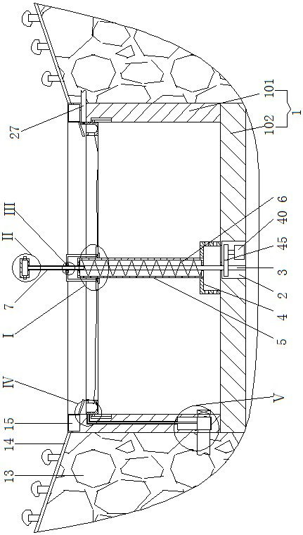
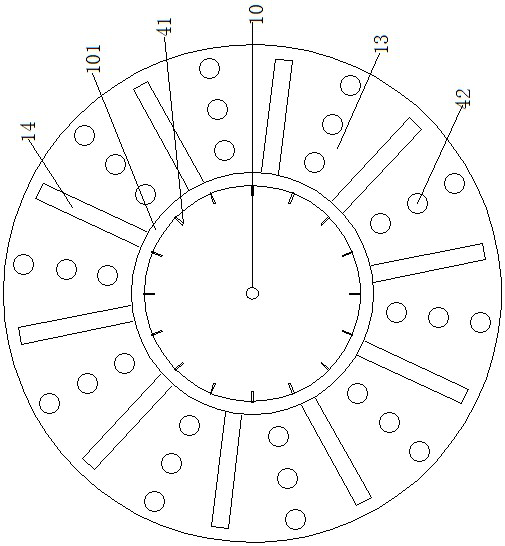
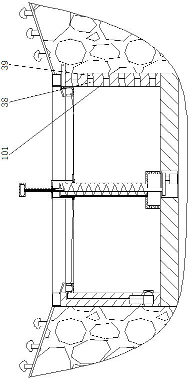
[0017]A water circulation device for sponge city landscape, as shown in the figure, includes a pool 1, the side of the pool 1 is an annular enclosure layer 101, the bottom of the pool 1 is a concrete layer 102, and the inner center of the concrete layer 102 is provided with an inner cavity 2 , the bottom bearing of the inner chamber 2 is connected...


PUM


Abstract

A water circulation device for sponge city landscape, including a pool, the side of the pool is an annular barrier layer, the bottom of the pool is a concrete layer, the inner center of the concrete layer has an inner cavity, the bottom of the inner cavity is connected to a vertical shaft, and there is a driving component in the inner cavity , the vertical axis is connected to the vertical pipe, the upper end of the vertical pipe is connected to the water spray tube, there is a water spray hole on the outside of the water spray tube, there is a nozzle on the outside of the water spray hole, there is an annular planting belt on the outside of the pool, and plants are planted on the planting slope of the annular planting belt, There is an annular water storage cavity inside the annular enclosure layer, and a water supply pipe is provided at the lower part of the annular enclosure layer, and the water supply pipe is connected with a water supply device. The upper part of the annular enclosure layer has a hole and an overflow pipe is arranged in the hole. In rainy days, the present invention uses the annular water storage cavity and the pool together to achieve the effect of water storage and drainage. When used in dry weather, the plants are distributed around the annular pool through the setting of the annular planting belt, so that the annular water spray canister can All the plants play a watering role, thereby ensuring the water source required for the normal growth of the plants.

Description

technical field [0001] The invention belongs to the field of sponge city landscape devices, in particular to a water circulation device for sponge city landscapes. Background technique [0002] Sponge city is a new generation of urban stormwater management concept. It means that the city can be like a sponge, and has good elasticity in adapting to environmental changes and dealing with natural disasters caused by rainwater. It can also be called "water elastic city". The international general term is "low-impact development rainwater system construction". When it rains, water is absorbed, stored, infiltrated, purified, and the stored water is released and utilized when needed. It can be seen everywhere in parks and green spots in the city. Parks and Greening points can beautify the city and improve the air quality of the city, but the current green belts have poor water seepage and water storage capacity in response to rainy days, which will cause surface runoff, making it i...

Claims


Application Information

Patent Timeline
Patent Type & Authority Patents(China)
IPC IPC(8): E03F5/10E03F5/14A01G25/02
CPCE03F5/101E03F5/14A01G25/02Y02A40/22
Inventor 李玮张丽娟
Owner 重庆泛奥园林景观设计有限公司
Learn More