Semiconductor refrigeration device
A refrigeration device and semiconductor technology, applied in refrigerators, refrigeration components, refrigeration and liquefaction, etc., can solve the problems of limited cooling effect, lower body temperature, and high cost, so as to improve human comfort, reduce ambient temperature, and improve service life. Effect
- Summary
- Abstract
- Description
- Claims
- Application Information
AI Technical Summary
Problems solved by technology
Method used
Image
Examples
Embodiment 1
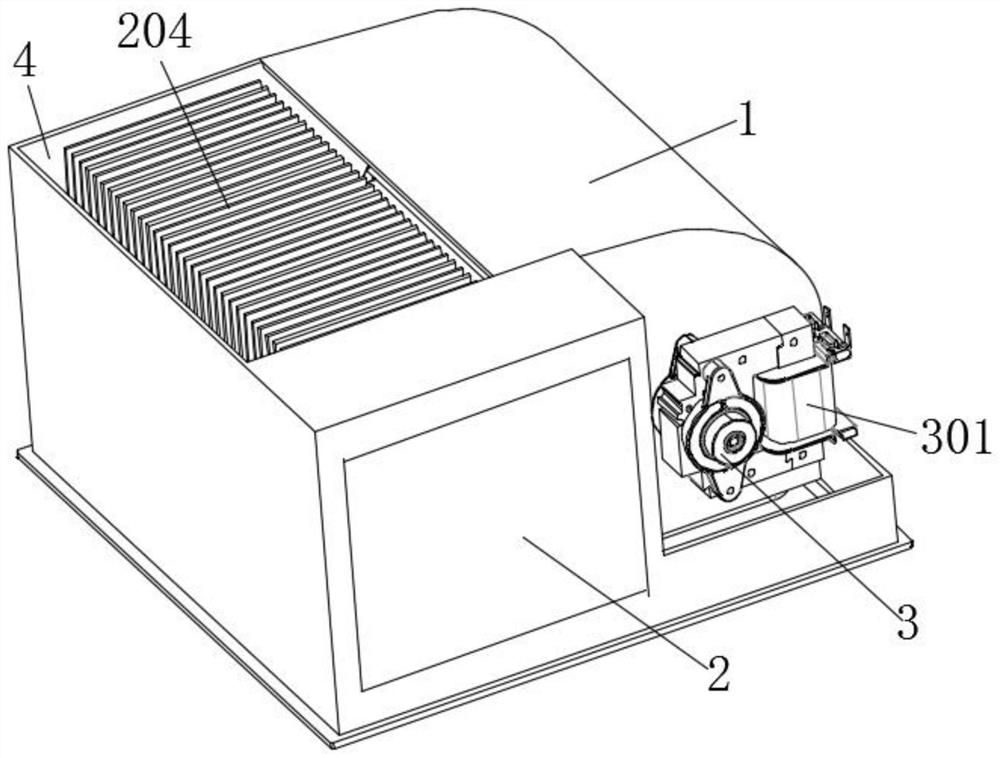
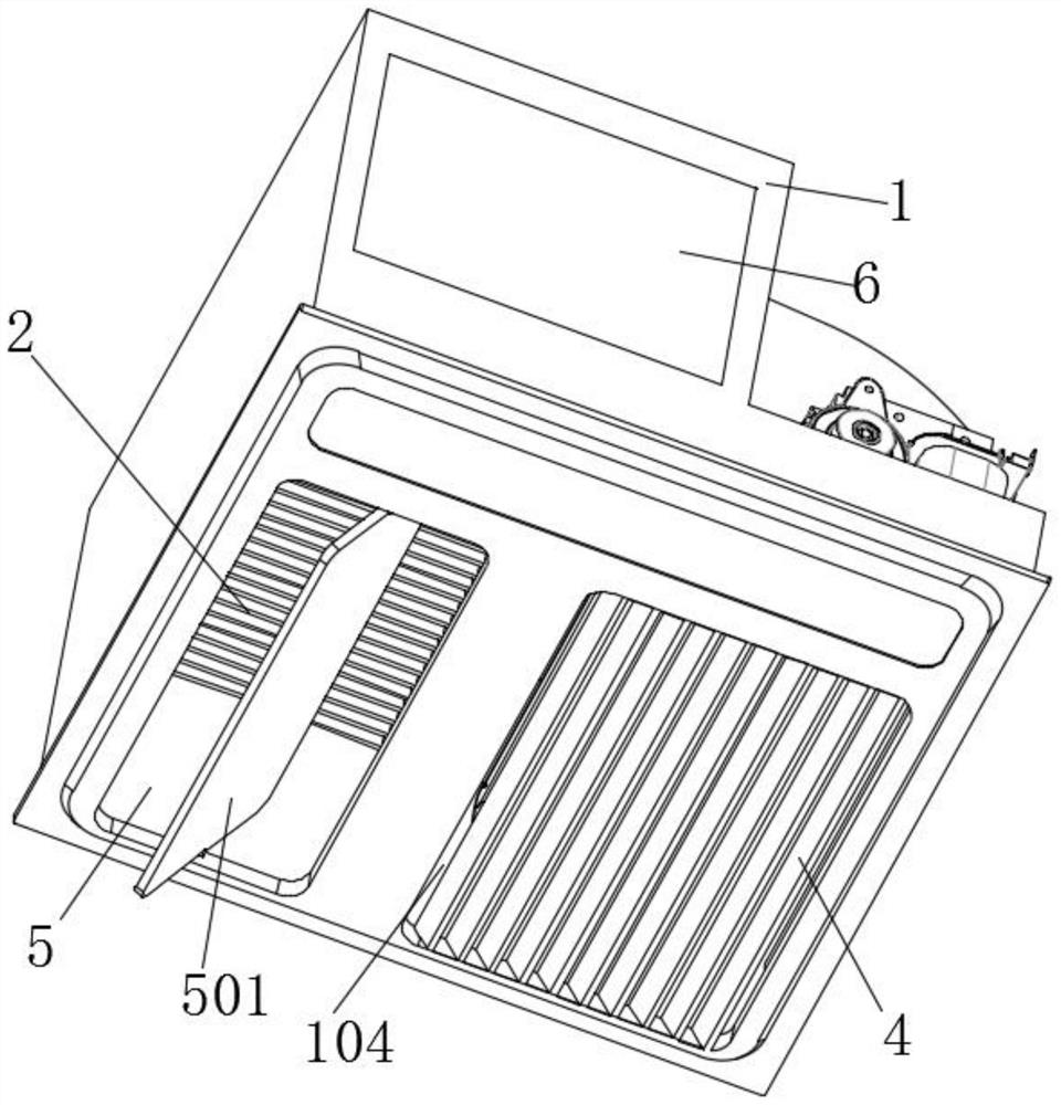
[0030] refer to figure 1 , figure 2 As shown, the present invention is a semiconductor refrigeration device, which includes a housing 1 , a refrigeration assembly 2 , a fan assembly 3 , a cooling outlet 4 , an air outlet 5 and a power supply module 6 .
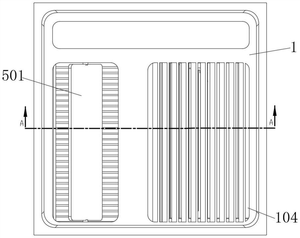
[0031] The bottom of the casing 1 is provided with an air inlet 104 for introducing outdoor fresh air. The air inlet 104 is provided with a plurality of baffles 103 to form several air inlet passages. The baffles 103 are arranged in parallel. A certain angle is formed between them to increase the air intake area.
[0032] refer to image 3 , Figure 4 As shown, the cooling assembly 2 includes a semiconductor cooling sheet 201 with a cold end and a hot end, the cooling assembly 2 is arranged on the inner side wall of the housing 1, and a cooling channel near the cold end and a heat dissipation channel near the hot end are formed in the cooling assembly 2; 2 also includes a cold-end cooling fin group 202 and a hot-end heat ...
Embodiment 2
[0042] refer to figure 1 , figure 2 As shown, the present invention is a semiconductor refrigeration device, which includes a housing 1 , a refrigeration assembly 2 , a fan assembly 3 , a cooling outlet 4 , an air outlet 5 and a power supply module 6 .
[0043] The bottom of the casing 1 is provided with an air inlet 104 for introducing outdoor fresh air. The air inlet 104 is provided with a plurality of baffles 103 to form several air inlet passages. The baffles 103 are arranged in parallel. A certain angle is formed between them to increase the air intake area.
[0044] refer to image 3 , Figure 4 As shown, the cooling assembly 2 includes two semiconductor cooling fins 201 with a cold end and a hot end, the cooling assembly 2 is arranged on the inner side wall of the housing 1, and a cooling channel near the cold end and a heat dissipation channel near the hot end are formed in the cooling assembly 2; The assembly 2 also includes a cold-end cooling fin group 202 and a...
Embodiment 3
[0052] Compared with Embodiments 1 and 2, the difference is that, refer to Figure 6 , Figure 7 As shown, the cold-end cooling fin group 202 is arranged in the cooling channel and is connected with a conduit 204, one end of the conduit 204 is connected to the cold end of the semiconductor cooling chip 201, and the cold-end cooling fin group 202 is equipped with a first fan 205 The hot end cooling fin group 203 is arranged in the heat dissipation passage and connects the hot end of the semiconductor cooling fin 201, the hot end cooling fin group 203 upper surface is provided with a second fan 206, and the cooling capacity of the semiconductor cooling fin 201 cold end passes through the conduit 204 is guided to the hot-end cooling fin set 203, and the cold energy is blown out with the wind by the second fan 206.
PUM
 Abstract
Description
Claims
Application Information
 - R&D
- Intellectual Property
- Life Sciences
- Materials
- Tech Scout
- Unparalleled Data Quality
- Higher Quality Content
- 60% Fewer Hallucinations
Browse by: Latest US Patents, China's latest patents, Technical Efficacy Thesaurus, Application Domain, Technology Topic, Popular Technical Reports.
© 2025 PatSnap. All rights reserved.Legal|Privacy policy|Modern Slavery Act Transparency Statement|Sitemap|About US| Contact US: help@patsnap.com


