
Techniques for magnetic shielding of an optical isolator to maintain nominal magnetic flux density and a transmitter or transceiver system implementing same

一种光收发器、光隔离器的技术,应用在光学通信领域,能够解决光隔离器输出功率下降等问题

Pending Publication Date: 2021-04-13
APPLIED OPTOELECTRONICS
View PDF4 Cites 3 Cited by
  • Summary
  • Abstract
  • Description
  • Claims
  • Application Information

AI Technical Summary

Problems solved by technology

However, when exposed to the magnetic field of the optoisolator, components of the light emitting subassembly, such as metal housings, become magnetized, which may adversely affect the magnetic flux density of the optoisolator's magnetic field
This essentially reduces the output power of the optoisolator

Method used


Image

  • Techniques for magnetic shielding of an optical isolator to maintain nominal magnetic flux density and a transmitter or transceiver system implementing same
  • Techniques for magnetic shielding of an optical isolator to maintain nominal magnetic flux density and a transmitter or transceiver system implementing same
  • Techniques for magnetic shielding of an optical isolator to maintain nominal magnetic flux density and a transmitter or transceiver system implementing same

Examples


Embodiment Construction

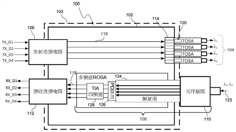
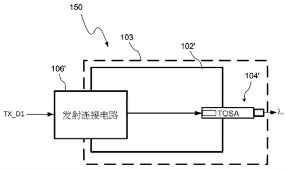
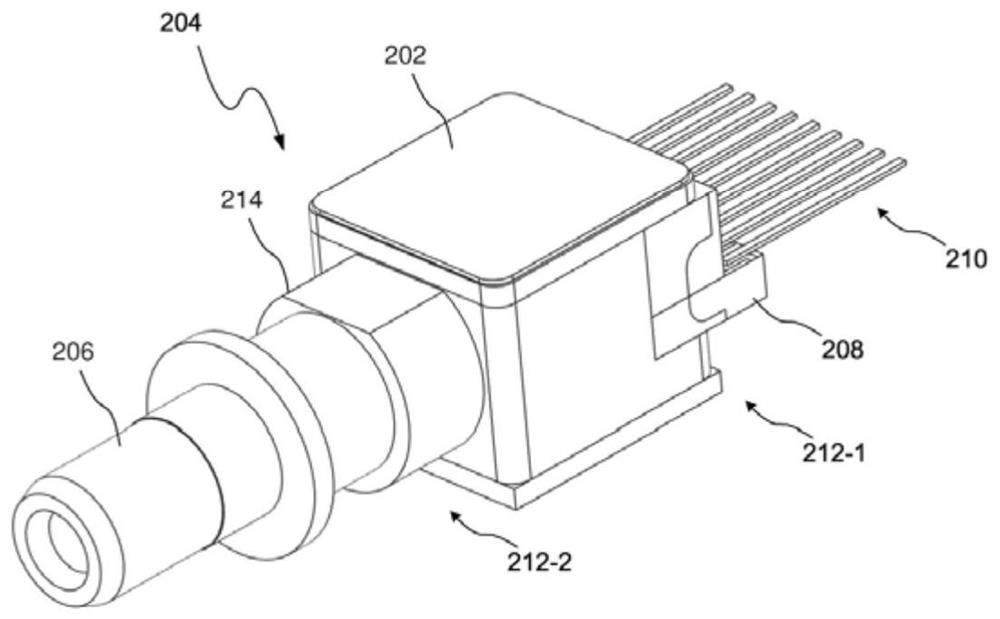
[0057] In general, the present invention is directed to a transmit optical subassembly (TOSA) for an optical transceiver or transmitter, wherein the transmit optical subassembly includes a magnetically shielded optical isolator to minimize or reduce exposure to Possibility of magnetizing components of the light emitting subassembly due to the associated magnetic field of the optoisolator. Embodiments of the invention include a light emitting subassembly housing of a magnetic shield at least partially surrounding the optical isolator, and the magnetic shield reflects / directs associated magnetic energy away from potentially magnetized components.

[0058] In one embodiment, the magnetic shield comprises a substantially cylindrical body with a cavity extending therebetween, wherein the cavity is shaped / contoured to securely position the optical isolator and associated magnets in relation to the optical The location where the light path of the emit subcomponent is aligned. To thi...


PUM

PropertyMeasurementUnit
coefficient of thermal expansionaaaaaaaaaa

Abstract

In general, the present disclosure is directed to a transmitter optical subassembly (TOSA) module for use in an optical transceiver or transmitter that includes a magnetically-shielded optical isolator to minimize or otherwise reduce magnetization of TOSA components. An embodiment of the present disclosure includes a TOSA housing with magnetic shielding at least partially surrounding an optical isolator, with the magnetic shielding reflecting associated magnetic energy away from components, such as a metal TOSA housing or components disposed therein, that could become magnetized and adversely impact the magnetic flux density of the magnetic field associated with the optical isolator.

Description

technical field [0001] The present invention relates to optical communications, and more particularly to techniques for magnetically shielding optical isolators to reflect / direct their associated magnetic fields away from electrically sensitive and / or easily magnetized components such as metal housings. Background technique [0002] The optical transceiver is used for transmitting and receiving optical signals, and is suitable for but not limited to various applications such as internet data center, cable TV broadband and fiber to the home (FTTH). For example, optical transceivers can provide higher speeds and greater bandwidth over longer distances than transmission over copper cables. In aspects such as maintaining optical efficiency (power), thermal management, insertion loss, and manufacturing yield, the need to provide higher speeds at lower costs in smaller optical transceiver modules is challenging. [0003] The optical transceiver module and the transmitter module ...

Claims


Application Information

Patent Timeline
Patent Type & Authority Applications(China)
IPC IPC(8): G02B6/42
CPCG02B6/4246G02B6/4277G02B6/4208G02B6/4207H04B10/802H04B10/40H04J14/0287H04B10/501H05K9/0058
Inventor 王冲林恺声梁永宣何宜龙
Owner APPLIED OPTOELECTRONICS
Features
  • Generate Ideas
  • Intellectual Property
  • Life Sciences
  • Materials
  • Tech Scout
  • Unparalleled Data Quality
  • Higher Quality Content
  • 60% Fewer Hallucinations
Learn More