Power conversion circuit, control method of power conversion circuit and transformer

A conversion circuit and control method technology, applied in the fields of transformers and power conversion circuits, can solve the problems of high closed power, high cost, and large device size, and achieve the effect of improving reliability and avoiding current impact.

Pending Publication Date: 2021-04-13
HUAWEI DIGITAL POWER TECH CO LTD
View PDF3 Cites 1 Cited by
  • Summary
  • Abstract
  • Description
  • Claims
  • Application Information

AI Technical Summary

Problems solved by technology

[0005] It is not difficult to see from the above introduction that when the SST is started, a large current will flow through T1, T2, and T3 at the moment when T1, T2, and T3 are closed, so the closing power of T1, T2, and T3 is relatively large, which will cause T1 , T2, T3 devices are large in size, high in cost, and also have reliability risks

Method used


Image

  • Power conversion circuit, control method of power conversion circuit and transformer
  • Power conversion circuit, control method of power conversion circuit and transformer
  • Power conversion circuit, control method of power conversion circuit and transformer

Examples


Embodiment Construction

[0044] In order to make the purpose, technical solution and advantages of the application clearer, the application will be further described in detail below in conjunction with the accompanying drawings.

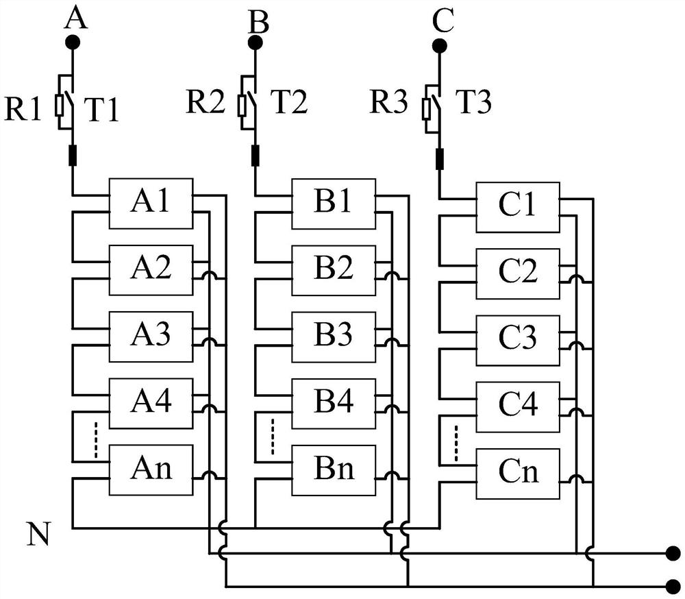
[0045] The embodiment of the present application provides a power conversion circuit, such as Figure 4 As shown, the power conversion circuit 400 includes at least one first power conversion unit 401 connected in series with the first phase line, at least one second power conversion unit 402 connected in series with the second phase line, and at least one second power conversion unit 402 connected in series with the third phase line at least one third power conversion unit 403; in addition, the power conversion circuit 400 also includes a plurality of first start-up circuits 404 and a plurality of second start-up circuits 405, and a plurality of first start-up circuits 404 are connected in series on the first phase line, Each first starting circuit 404 includes a first rela...


PUM


Abstract

An embodiment of the invention provides a power conversion circuit, a control method of the power conversion circuit and a transformer, which are used for reducing the size of a device in the power conversion circuit and improving the reliability of a system. The power conversion circuit comprises at least one first power conversion unit connected to a first phase line in series, at least one second power conversion unit connected to a second phase line in series, at least one third power conversion unit connected to a third phase line in series, a plurality of first starting circuits connected to the first phase line in series, and a plurality of second starting circuits connected to the second phase line in series, wherein each first starting circuit comprises a first relay and a first resistor which are connected in parallel, and the first relay in each first starting circuit is sequentially closed after the power conversion circuit is powered on and is used for starting the power conversion circuit; and each second starting circuit comprises a second relay and a second resistor which are connected in parallel, and the second relay in each second starting circuit is sequentially closed after the power conversion circuit is powered on and is used for starting the power conversion circuit.

Description

technical field [0001] The present application relates to the technical field of power electronics, and in particular to a power conversion circuit, a control method for the power conversion circuit, and a transformer. Background technique [0002] Solid-state transformers (solid-state transformers, SST) are a combination of power electronic conversion technology and high-frequency power conversion technology based on the principle of electromagnetic induction, and realize the transformation of electric energy with one power characteristic into another power characteristic. Static electrical equipment. Compared with conventional transformers, SST can realize flexible control of primary side current, secondary side voltage and power. [0003] Such as figure 1 Shown is a schematic structural diagram of an SST. In this SST, the input of the three phases A, B, and C are all 10kV AC voltage. In each phase, a resistor and a relay (also called a contactor) connected in parallel...

Claims


Application Information

Patent Timeline
IPC IPC(8): H02M5/10H02M1/36
CPCH02M5/10H02M1/36H02M1/007H02M7/49H02M1/0074H02M7/4807H02M1/0085
Inventor 黄朱勇张晓飞帅鹏刘培国
Owner HUAWEI DIGITAL POWER TECH CO LTD
Why Eureka
Try Eureka