Metal rod body curling device and working method thereof

A technology of a crimping device and a working method, applied in the field of metal processing devices, can solve the problems of time-consuming and laborious, achieve the effects of solving the time-consuming and laborious, realizing signal control, and improving work efficiency

Active Publication Date: 2021-04-16
河北东润紧固件有限公司
View PDF8 Cites 0 Cited by
  • Summary
  • Abstract
  • Description
  • Claims
  • Application Information

AI Technical Summary

Problems solved by technology

[0007] The beneficial effects of the above scheme are: through the cooperative action of the parts, a curled structure can be formed on the rotating rod, and when the curled structure is formed, the curled structure can also be formed into a spiral curled structure through the thread structure, which improves the work efficiency and solves the problem of Solved the time-consuming and labor-intensive problem of manual crimping

Method used


Image

  • Metal rod body curling device and working method thereof
  • Metal rod body curling device and working method thereof
  • Metal rod body curling device and working method thereof

Examples


no. 1 example

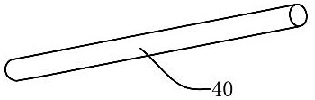
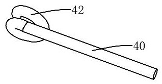
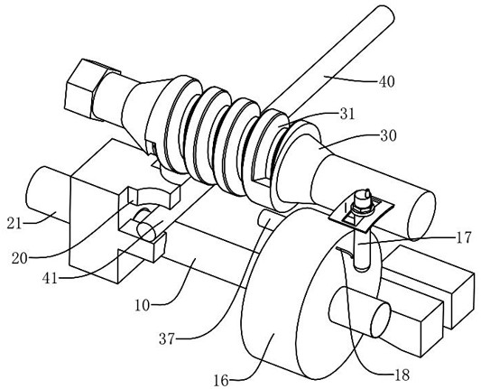
[0054] Such as image 3 with Figure 4 As shown, the present invention provides a metal rod crimping device, which includes a rotating rod 10, a clamping member 20 and a pressing rod 30; the rotating rod 10 is used to place the metal rod 40; the clamping member 20 is used to fix the metal rod 40 End 41; the pressing rod 30 is arranged on one side of the rotating rod 10, and the pressing rod 30 has a threaded structure 31, and the threaded structure 31 has a spiral oblique thread groove, and the oblique thread groove can drive the metal rod body 40 to curl move during the process.

[0055] The crimping method of the metal rod crimping device provided by the present invention comprises the following steps:

[0056] S1: Put a metal rod 40 on the rotating rod 10, and the pressing rod 30 is located on the upper part of the metal rod 40, and the end 41 of the metal rod 40 is pressed by the engaging part 20;

[0057] S2: Drive the rotating rod 10 to rotate, and force the metal rod...

no. 2 example

[0060] As a preferred embodiment, such as Figure 5 to Figure 9 As shown, the metal rod crimping device includes a frame 11, and the frame 11 has an accommodating space 12; in the accommodating space 12, the frame 11 has a first side wall 13 and a second side wall 14 that are oppositely arranged; It has a protruding rod 21, a joint 22 and a protruding structure 23, the joint 22 is used to detachably fit and connect with the first end of the rotating rod 10, and the protruding structure 23 is arranged on one side of the joint 22; the rotating rod 10 The second end of the second end is arranged on the first side wall 13, and one end of the extension rod 21 is arranged on the second side wall 14; before starting the rotation rod 10 to drive, the extension rod 21 is first driven to drive the junction 22 to the rotation rod 10 The first end of the extension rod 21 is extended and moved, and the joint 22 of the end of the extension rod 21 is connected and matched with the first end ...


PUM


Abstract

The invention relates to a metal rod body curling device and a working method thereof. The metal rod body curling device comprises a rotating rod, a clamping piece and a pressing rod. The rotating rod is used for containing a metal rod body. The clamping piece is used for fixing the end portion of the metal rod body. The pressing rod is arranged on one side of the rotating rod and provided with a threaded structure. By means of the cooperation effect of the components, a curling structure can be formed on the rotating rod, the curling structure can form a spiral curling structure through the threaded structure while the curling structure is formed, the working efficiency is improved, and the problem that time is consumed and labor is wasted when manual curling is conducted is solved.

Description

technical field [0001] The invention relates to a metal processing device, in particular to a device structure and a processing method capable of curling a metal rod body. Background technique [0002] Metal fittings, iron or aluminum metal accessories widely used in transmission lines, are collectively referred to as fittings. Most of the fittings need to withstand large tension during operation, and some of them also need to ensure good electrical contact. In electric fittings or other occasions, a metal pipe body with a crimped structure is often used. [0003] Such as figure 1 Shown is an existing metal structure, that is, a metal rod body 40, such as figure 2 As shown, after processing, it forms a crimped structure 42 at the end, and the process of forming the crimped structure 42 is generally formed by crimping a straight metal tube. It has been found in practice that such a crimped structure is difficult to process, resulting in low process efficiency and high pr...

Claims


Application Information

Patent Timeline
Patent Type & Authority Applications(China)
IPC IPC(8): B21D11/06
Inventor 赵永波
Owner 河北东润紧固件有限公司
Why Eureka
Try Eureka