High-pressure pneumatic boosting take-off device for light unmanned aerial vehicle

A high-height and light-weight technology, applied in the field of drones, can solve problems such as air pollution economy, hidden safety hazards, and large energy consumption

Active Publication Date: 2021-04-16
ZHONGXIN HANCHUANG BEIJING TECH CO LTD
View PDF10 Cites 1 Cited by
  • Summary
  • Abstract
  • Description
  • Claims
  • Application Information

AI Technical Summary

Problems solved by technology

[0006] In order to solve the above technical problems, the present invention provides a light unmanned aerial vehicle high-pressure pneumatic booster take-off device to solve the existing booster take-off device, UAV Every time during the take-off process, the UAV needs to be assisted to fly into the air, and the UAV has to consume a lot of energy every time it takes off. When using the take-off device, improper operation is prone to safety hazards. Not only the air is polluted but also problems that cause economic loss

Method used


Image

  • High-pressure pneumatic boosting take-off device for light unmanned aerial vehicle
  • High-pressure pneumatic boosting take-off device for light unmanned aerial vehicle
  • High-pressure pneumatic boosting take-off device for light unmanned aerial vehicle

Examples


Embodiment

[0032] as attached figure 1 to attach Figure 7 Shown:

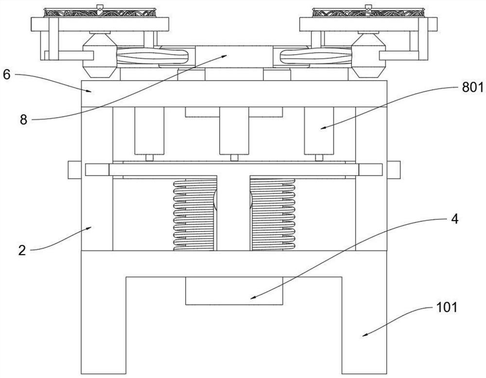
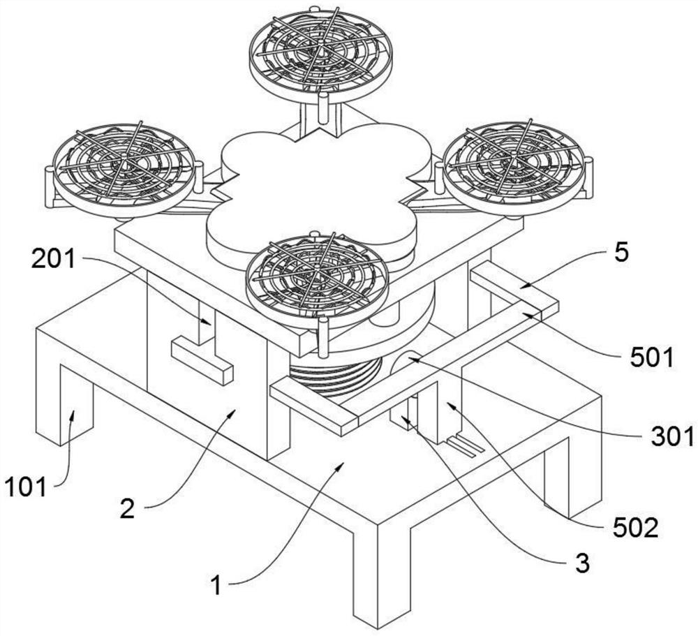
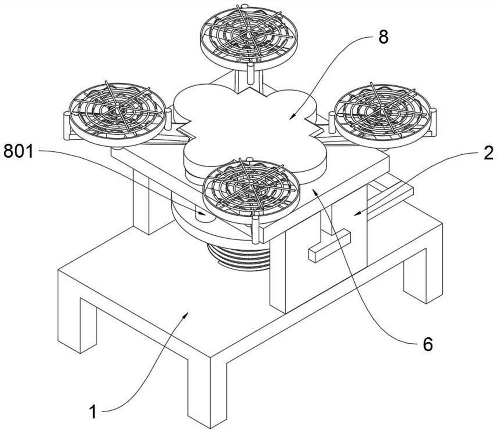
[0033] The present invention provides a light-duty unmanned aerial vehicle high-pressure pneumatic booster take-off device, including a bottom plate 1; the left and right ends of the top plane of the bottom plate 1 are fixed with vertically upward fixing plates 2; The bottom plate 1 includes a support column 101 and a limiting groove 102. The front and rear ends of the bottom plate 1 are fixedly equipped with support columns 101 that are vertically downward and symmetrical to each other. The plate 2 includes a guide hole 201 and a socket 202. The middle upper ends of the two fixed plates 2 are provided with a rectangular guide hole 201, and the right ends of the two fixed plates 2 are provided with a socket 202. The front end of the top plane of the bottom plate 1 is fixed. Install a vertically upward support 3; the top of the support 3 offers an arc-shaped groove; the support 3 includes an electric cylinder 301, and a...


PUM


Abstract

The invention provides a high-pressure pneumatic boosting take-off device for a light unmanned aerial vehicle, relates to the technical field of unmanned aerial vehicles, and aims to solve the problems that in each take-off process of an existing boosting take-off device, the unmanned aerial vehicle needs boosting to fly to the air, a large amount of energy is consumed during each take-off of the unmanned aerial vehicle, and the energy consumption is high. When the take-off device is used, potential safety hazards are likely to occur due to improper operation, air is polluted, and economic losses are caused. The device comprises a bottom plate. And vertically upward fixing plates are fixedly mounted at the left end and the right end of the top plane of the bottom plate. When the two inserting rods slide out of the rectangular holes of the guide rods, the spring columns can bounce upwards quickly, the bearing plate and the unmanned aerial vehicle above the bearing plate can be ejected upwards at the same time, the unmanned aerial vehicle is emptied and then commanded by a remote controller, and when the spring columns are ejected quickly, upward impact force of the bearing plate is blocked by the buffer blocks due to overlarge force.

Description

technical field [0001] The present invention relates to the technical field of unmanned aerial vehicles, and more specifically relates to a high-pressure pneumatic-assisted take-off device for light unmanned aerial vehicles. Background technique [0002] Unmanned aircraft, referred to as "UAV", is an unmanned aircraft that is controlled by radio remote control equipment and its own program control device, or is completely or intermittently operated autonomously by an on-board computer. [0003] There are many existing booster takeoff devices such as a light-duty UAV high-pressure pneumatic booster takeoff device in the patent application CN201910243978.3. The nose of the UAV is set horizontally to the left, and the lower surface of the UAV body is equipped with a cylinder. The accommodation tank includes a high-pressure gas cylinder, a cylinder plug shell, a piston, a one-way charging nozzle and a plug. The two ends of the cylinder plug shell are open, and the left end of th...

Claims


Application Information

Patent Timeline
Patent Type & Authority Applications(China)
IPC IPC(8): B64F1/06
Inventor 陆颖怡
Owner ZHONGXIN HANCHUANG BEIJING TECH CO LTD
Why Eureka
Try Eureka